07 The Self-Made Sensing Module
After a rigorous searching on the internet, I could not find a suitable sensing module that can serve my purpose. However, these are readily available for 12-volt or higher voltage batteries. So, I made one for myself.
I was looking for the following properties in the Sensing Module –
- It should trigger twice, once for a higher voltage, other for a lower voltage.
- It should trigger a relay and a green LED when it senses above 6.8±0.05 volts.
- The relay should latch once triggered and reset upon switching off the charger.
- It should trigger a red LED when it senses 5.0±0.05 volts.
- It should be able to detect the voltage change at the resolution of 0.1-volt or lower.
- It should be operable between 4.0-7.0 volt ranges.
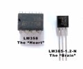
After tinkering ideas with 555 timer IC, some flip-flops, op-amps and transistors, I zeroed on LM358B Dual Comparator IC as the heart of the Sensing Module. Being a comparator, the low input offset voltage of 0.3 mV makes it fast responding. Also, it can operate at a minimum of 3.0 volts. After several rounds of experimentations, I prepared the following circuit schematic –

If I consider LM358B as the heart of the circuit, the LM385-1.2-N Precision Voltage Reference IC should be its brain. In practice, the LM385-1.2-N acts as a diode providing a precise reference voltage of 1.235 volts. It also consumes a very low amount of current (10 μA to 20 mA) during operation. Fundamentally, the circuit is a precision comparator that compares the scaled-down version of the battery pole voltage with the reference voltage and suitably triggers the output(s) of the op-amp during a voltage mismatch between two inputs.
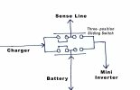
Let’s have a brief discussion about the working of the circuit. The circuit reads the battery pole voltage via the sense line. It also powers the module. The sense line is connected to the switch of the unit in such a way so that it can sense both the charging and discharging voltage of the battery.


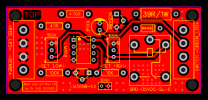
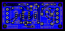
Each half of the LM358B detects high and low voltage, respectively. Pins 5, 6 and 7 are used for the high voltage detection. The fixed reference voltage is supplied to the inverting input (pin 6). The battery pole voltage is scaled-down using the R6 potentiometer and it was fed to the non-inverting input (pin 5). R6 sets a triggering threshold voltage for LM358B. The careful setting of R6 keeps the voltage of the non-inverting input (pin 5) lower than the inverting input (pin 6) during charging and the IC’s output remain low. As soon as the charging completes, the sensor line receives 6.8±0.05 volts from the battery pole and makes the voltage of the non-inverting input (pin 5) slightly higher than the inverting input (pin 6). This minute voltage difference between the two inputs is enough to trigger the IC’s output at pin 7 high. The non-rail-to-rail LM358B outputs around 5.5±0.05 volts at this stage. This voltage simultaneously triggers the relay and the Green LED via the driver transistor Q1 (BC548B). The R4 and R5 are the current limiting resistors for the relay and the LED, respectively. C1 prevents false pre-triggering of the LED. D1 protects the relay from back EMF. Upon the start of the transistor’s conduction, both the relay and the LED turn on. Pin 2, 3 and 5 are the switch points of the relay. Pin 3 and 5. The battery is connected to the system via the path of Pins 3 and 5 which are normally-close points of the relay. Upon conduction of the relay, it disconnects pin 3 and 5, thereby disengaging the charger circuitry from the battery. The charger is so designed that the charging terminal provides power to the “Sense Module” even after battery-charger disengagement. It keeps the relay engaged creating a latch. The latch resets and the battery terminals reconnect when the charger is powered off.
Pins 1, 2 and 3 forms a part of the low voltage detection circuitry where the fixed reference voltage is supplied to the non-inverting input (pin 3) and the scaled-down battery pole voltage is fed to the inverting input (pin 2) via the R7 potentiometer. This circuitry acts during the use of the Emergency Light when the battery discharges. The low threshold is configured in such a way that during the satisfactory charge status of the battery, it keeps the voltage of the non-inverting input (pin 3) higher than the supplied reference voltage at the inverting input (pin 2), keeping the output (pin 1) low. When the battery voltage becomes lower than 5-volt, the non-inverting input (pin 3) becomes higher than the inverting input (pin 2) driving the output (pin 1) high. The output drives the Red LED indication of the LOW Battery status until the battery voltage reduces to 3-volt. The minimum operating voltage for both LM358 and the LED is 3-volt. Therefore, the low voltage detection circuitry remains alive until this battery voltage.
During the prototype testing, the circuit reported 0.02-volt sensitivity. The means that the circuit responses at ±0.02-volt of the predefined threshold voltages. Initially, I tried several low-voltage Zener diodes, general-purpose op-amps and transistor-based circuits. But there were several drawbacks. Firstly, Zeners are not as precise as the reference diode. Secondly, they consume a lot more current than precision diode creating inefficiency during the low voltage point detection. Thirdly, the circuit works well when a low reference voltage is used; Zeners below 3.3 volts are not available. On the other hand, the general-purpose op-amps (and also transistors) decrease the sensitivity of the circuit. Their higher input offset voltage decreases the triggering precision of the circuitry.


