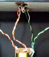
My affordable LM3886 DIY amplifier.

Hiten

Well-Known Member
Joined
Oct 17, 2008
Messages
3,242
Points
113
Location
Kalyan
Hello folks,
This is my fun, getting hands dirty DIY LM3886 amplifier. It was started during lockdown, as I had nothing to do. But later got busy so finished it when time permitted. I have no knowledge of proper electronics so cant answer technical questions. But ask me other things. As some of you know I just build to listen to the sound and move on. So this amplifier will be on sale soon to fund my next DIY project. The amp works perfectly and sounds good. LM3886 is probably last class AB high quality IC. Specifications are great for 40 watts in to 8 ohms. My main goal was to build as cheap as possible and had budget of 5K which exceeded :p. But it is built with love.

Some details...
This LM3886 chinese module and most parts are from GTech audio (Tamil Nadu). Some parts they couriered by air which was not necessary. Overall good experience with Gtech Audio. Smaller chassis was chosen to save money so amp is little bit congested inside. And I misjudged speaker terminal space from modules. But it is manageable. There are details after some picture and cost of the project, which probably will be helpful to new diyers like me. Audio CD will give you some perspective.
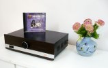
LM3886 A.jpg

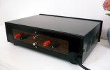
LM3886 backpanel.jpg

LM3886 B.jpg

LM3886 innard 2.jpg
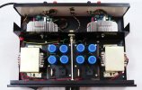
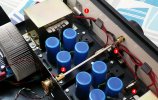
(1) Power on light and wire routing aluminum clips. (2) Extension shaft from robotics project (3) Mains Terminal to fuses and transformer from AC mains. There is plastic film below PS boards. (4) 1.5A fuse for each channel. Earlier I had two pole on/off switch but it broke so am using single pole switch for live wire. Separate fuse on two PS board. There is also an extra third main fuse.

LM3886 innard1.jpg
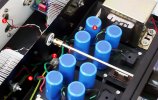
(5) Capacitor from Input ground to chassis to attenuate RF (6) Grommet from CD player mechanism (mains in has turntable grommet (7) PS 0v two wires and mains earth wire grounded to Amplifier main chassis (8) Four 4700uf Caps. per channel. Silly me I thought caps would get hot so removed original sleeves then put on new one realizing the outer capacitor case will be carrying voltages.

misc.jpg

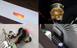
(Top Left) Power on light made from LED TV backlight bulb plastic. (Top Right) 10 K volume pot made fake logarithmic with a resistor. (Bottom Left) Speaker Terminals. (Bottom Right) Aluminum piece is on IC just for countersunk hole for screw.

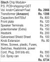
Approximate build cost.
build cost.jpg


:)
Thanks for watching. Suggestions welcome and will be highly appreciated.
Regards
 
Last edited:
You should be very proud of a very well made project! Congratulations!

Edit: I don't understand the cap from input ground to chassis though! Is that a ceramic cap? What value?
 
Last edited:
Nicely done amplifier, congrats on the beauty. Lockdown has got our inner passions out.

What are the speakers paired with it, would like to know how does it sound according to you.
Why selling it so soon?
 
Hello folks,
This is my fun, getting hands dirty DIY LM3886 amplifier. It was started during lockdown, as I had nothing to do. But later got busy so finished it when time permitted. I have no knowledge of proper electronics so cant answer technical questions. But ask me other things. As some of you know I just build to listen to the sound and move on. So this amplifier will be on sale soon to fund my next DIY project. The amp works perfectly and sounds good. LM3886 is probably last class AB high quality IC. Specifications are great for 40 watts in to 8 ohms. My main goal was to build as cheap as possible and had budget of 5K which exceeded :p. But it is built with love.

Some details...
This LM3886 chinese module and most parts are from GTech audio (Tamil Nadu). Some parts they couriered by air which was not necessary. Overall good experience with Gtech Audio. Smaller chassis was chosen to save money so amp is little bit congested inside. And I misjudged speaker terminal space from modules. But it is manageable. There are details after some picture and cost of the project, which probably will be helpful to new diyers like me. Audio CD will give you some perspective.
View attachment 64718

View attachment 64719

View attachment 64720

View attachment 64721
(1) Power on light and wire routing aluminum clips. (2) Extension shaft from robotics project (3) Mains Terminal to fuses and transformer from AC mains. There is plastic film below PS boards. (4) 1.5A fuse for each channel. Earlier I had two pole on/off switch but it broke so am using single pole switch for live wire. Separate fuse on two PS board. There is also an extra third main fuse.

View attachment 64722
(5) Capacitor from Input ground to chassis to attenuate RF (6) Grommet from CD player mechanism (mains in has turntable grommet (7) PS 0v two wires and mains earth wire grounded to Amplifier main chassis (8) Four 4700uf Caps. per channel. Silly me I thought caps would get hot so removed original sleeves then put on new one realizing the outer capacitor case will be carrying voltages.

View attachment 64723

(Top Left) Power on light made from LED TV backlight bulb plastic. (Top Right) 10 K volume pot made fake logarithmic with a resistor. (Bottom Left) Speaker Terminals. (Bottom Right) Aluminum piece is on IC just for countersunk hole for screw.

Approximate build cost.
View attachment 64726


:)
Thanks for watching. Suggestions welcome and will be highly appreciated.
Regards

Beautifully done. Congrats.
 
The CPU heat sink might get really hot . The heatsinks are rated for around 70w power with active cooling . When using 4 ohm load they might get a bit too hot .
 
Hello folks,
This is my fun, getting hands dirty DIY LM3886 amplifier. It was started during lockdown, as I had nothing to do. But later got busy so finished it when time permitted. I have no knowledge of proper electronics so cant answer technical questions. But ask me other things. As some of you know I just build to listen to the sound and move on. So this amplifier will be on sale soon to fund my next DIY project. The amp works perfectly and sounds good. LM3886 is probably last class AB high quality IC. Specifications are great for 40 watts in to 8 ohms. My main goal was to build as cheap as possible and had budget of 5K which exceeded :p. But it is built with love.

Some details...
This LM3886 chinese module and most parts are from GTech audio (Tamil Nadu). Some parts they couriered by air which was not necessary. Overall good experience with Gtech Audio. Smaller chassis was chosen to save money so amp is little bit congested inside. And I misjudged speaker terminal space from modules. But it is manageable. There are details after some picture and cost of the project, which probably will be helpful to new diyers like me. Audio CD will give you some perspective.
View attachment 64718

View attachment 64719

View attachment 64720

View attachment 64721
(1) Power on light and wire routing aluminum clips. (2) Extension shaft from robotics project (3) Mains Terminal to fuses and transformer from AC mains. There is plastic film below PS boards. (4) 1.5A fuse for each channel. Earlier I had two pole on/off switch but it broke so am using single pole switch for live wire. Separate fuse on two PS board. There is also an extra third main fuse.
View attachment 64722
(5) Capacitor from Input ground to chassis to attenuate RF (6) Grommet from CD player mechanism (mains in has turntable grommet (7) PS 0v two wires and mains earth wire grounded to Amplifier main chassis (8) Four 4700uf Caps. per channel. Silly me I thought caps would get hot so removed original sleeves then put on new one realizing the outer capacitor case will be carrying voltages.
View attachment 64723

(Top Left) Power on light made from LED TV backlight bulb plastic. (Top Right) 10 K volume pot made fake logarithmic with a resistor. (Bottom Left) Speaker Terminals. (Bottom Right) Aluminum piece is on IC just for countersunk hole for screw.

Approximate build cost.
View attachment 64726


:)
Thanks for watching. Suggestions welcome and will be highly appreciated.
Regards
Very well done, I had heard the sound of the ic and it was good enough to drive my Arphi Acquarious. Congratulations btw, hope to see new projects ahead
 
@Keith
It culminated because I was clueless about star grounding. I think basic principle is all current should go to return wire to avoid ground loops and attennuate interference. I had read lots of article with confusing implementation. So asked in diyAudio HERE. It was months ago. I think from Bonsai and AndrewT's posts across various thread I finally decided to have only power supply 0v wires to chassis and 1nf Ceramic Capacitor at Input ground. Ceramic is necessary at this place. I have read article about it (Probably from Bonsai) Will have to search and post. Although this cap is not necessary and one can do without it.
@amrutmhatre90
1) This is probably my third build regardless of lockdown. Some of other uglier build I have not shared.
2) I dont take risks with DIY amps. Speakers were DIY, Sony boombox and single wide band driver. I found single speaker sounding good but I dont trust my ears. A friend here will be loaning me some speakers soon.
3) Amp is on duty for severeal months in chassis outside chassis.
@log21
I have throughly read all the articles. The choice of powersupply which is giving me +/-25v DC is safest for IC and amp running. I have run it for almost an hour without ceiling fan running in closed chassis at moderate volume. The Heatsinks barely gets warm. IC too is lightly warmer (not hot) after one hour. What you suggest is for amp running longer duration for low impedance speakers at moderately high volume.
@Bordoloi
This was affordable DIY I didnt spend much as goal was to build. So no toroidals.
@irv
No I hardly have knowledge. I was going to build SET Tube amp (had all the parts except OTs) but costs were running too high (for output transformers) for me. so was abandoned.
@ShantaramChari
I am lazy person. New project is not decided. It cound be preamp with tonecontrol, bookshelf speaker or anything else whichever clicks my mind and parts are easily available in my budget.
@yogibear
Thank you :)
Regards
 
Hello folks,
This is my fun, getting hands dirty DIY LM3886 amplifier. It was started during lockdown, as I had nothing to do. But later got busy so finished it when time permitted. I have no knowledge of proper electronics so cant answer technical questions. But ask me other things. As some of you know I just build to listen to the sound and move on. So this amplifier will be on sale soon to fund my next DIY project. The amp works perfectly and sounds good. LM3886 is probably last class AB high quality IC. Specifications are great for 40 watts in to 8 ohms. My main goal was to build as cheap as possible and had budget of 5K which exceeded :p. But it is built with love.

Some details...
This LM3886 chinese module and most parts are from GTech audio (Tamil Nadu). Some parts they couriered by air which was not necessary. Overall good experience with Gtech Audio. Smaller chassis was chosen to save money so amp is little bit congested inside. And I misjudged speaker terminal space from modules. But it is manageable. There are details after some picture and cost of the project, which probably will be helpful to new diyers like me. Audio CD will give you some perspective.

View attachment 64718

View attachment 64719

View attachment 64720

View attachment 64721
(1) Power on light and wire routing aluminum clips. (2) Extension shaft from robotics project (3) Mains Terminal to fuses and transformer from AC mains. There is plastic film below PS boards. (4) 1.5A fuse for each channel. Earlier I had two pole on/off switch but it broke so am using single pole switch for live wire. Separate fuse on two PS board. There is also an extra third main fuse.

View attachment 64722
(5) Capacitor from Input ground to chassis to attenuate RF (6) Grommet from CD player mechanism (mains in has turntable grommet (7) PS 0v two wires and mains earth wire grounded to Amplifier main chassis (8) Four 4700uf Caps. per channel. Silly me I thought caps would get hot so removed original sleeves then put on new one realizing the outer capacitor case will be carrying voltages.

View attachment 64723

(Top Left) Power on light made from LED TV backlight bulb plastic. (Top Right) 10 K volume pot made fake logarithmic with a resistor. (Bottom Left) Speaker Terminals. (Bottom Right) Aluminum piece is on IC just for countersunk hole for screw.

Approximate build cost.
View attachment 64726


:)
Thanks for watching. Suggestions welcome and will be highly appreciated.
Regards
Very well built. A list of links that your bought your posts from will help others too
 
@sdk
Do you mean speaker binding post ? I got from local electronics shop here. Except two items in bold on top of the list (From Gtech audio and Amazon) the rest I got from local shop only. Earlier I had seen speaker binding post on lamington road. Forgot the shop name but it is in champion rubber line Opposite pearl enterprises. But it was quite a few years back.
@joshua
Thanks. incidently the heatsinks took most of the effort. Had to drill 1 inch through hole. Broke few drill bits. Than bought expensive drill bit and slowly (With WD40 and Oil) managed to get it. There was also a metal piece Press fitted which I had to remove. Then the protruding part which held metal piece was removed. Then To keep heatsink stable on chassis floor I had to cut quarter inch of fins. Just like you see on top.
@Keith
I found the article. See link here. It is on page 52. (Thanks to Bonsai-DiyAudio).(A big Thanks to Cranky (Former FM) too. He was of great help)
Regards.
 
Last edited:
Lovely build and the best heat sink I have seen in any build till date. The only suggestion that I would have is to use twisted pair from a cat5/cat5e/cat6 cable from the input RCA to the input of the amp. It is only after I have acquired two LCR meters that I can say is that whatever dielectric these catx cables use, they are fantastic and give very low capacitance / meter and hence there will almost absolutely no HF frequency roll off in your build. The other cables that give low capacitance are the RG59, RG6 cables, but those can be cumbersome and inflexible.

Your build is probably the best I have seen on hifivision.

Can you provide the link to the E Transfomer? The finish looks so good. Are these Chinese? Whoever it is, the manufacturer has taken pride in having a good finish to his/her product.
 
Last edited:
mbhangui,
Thanks for compliments but pl. dont embarass me. I have seen FMs top notch builds which beats commercial amps.
Earlier I used cat 5 wire with 100K+10k R dummy log pot.(See old mobile phone pic attached). New wires are from childrens robotic hobby kit. Cant tell the sound quality as my hearing is not good. If you have noticed the whole layout is made such that wires from transformer Secondary to PS, from PS to amp module, Speaker wires from module to bindingpost and Input signal wires are hardly 2 to 3 inches. Twisted. Input wires float in the air. 2 set are near chassis metal floor and remaining 2 set in air which are close to top metal chassis when fitted.
Transformers are good. I like EI transformers form factor. They are from Amazon. Link HERE.

Regards
 

Attachments

  • cat.jpg
    cat.jpg
    122.7 KB · Views: 45
Transformers are good. I like EI transformers form factor. They are from Amazon. Link HERE.
The transformers that you have fitted look better than the image on the amazon link. Maybe you did some polishing. I also do the same to make things shine.
 
@Keith
I found the article. See link here. It is on page 52. (Thanks to Bonsai-DiyAudio).(A big Thanks to Cranky (Former FM) too. He was of great help)
Regards.
Thanks, Hiten! So, both channel input grounds bonded together at the RCA input end and that is connected to chassis via a 1nf Ceramic Capacitor. Got it!
Andrew also says that for power amplifiers, this should be implemented at the speaker output end. You didn't implement this at the outputs, did you?
 
mbhangui
No they are not polished. They are as it is. only stickers removed. By the way earlier they sent me only one transformer though I paid for two. After complaint to amazon they replaced.
Keith.
two 1nf caps for each channel from input ground to the chassis. I have not read about speaker output. Can you point out the page no.
thx
 
Keith.
two 1nf caps for each channel from input ground to the chassis.
Only one cap is needed - not one per channel. You bond the grounds from each channel together and then connect it to the chassis via one 1nf cap.
I have not read about speaker output. Can you point out the page no.
thx
In Andrew's pdf - Page 51, the 3rd bullet from top.
 
For excellent sound that won't break the bank, the 5 Star Award Winning Wharfedale Diamond 12.1 Bookshelf Speakers is the one to consider!
Back
Top