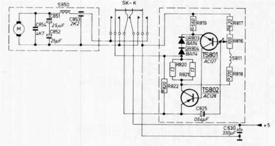
Caution: being a germanium design, the ground of the circuit is the (+) rail of the power supply and battery. The power supply diodes and in-circuit semiconductors (including diodes) are wired keeping this aspect in mind. The polarity of electrolytic capacitors will also appear to be in the opposite direction due to this (very important to note this if any recapping exercise is undertaken). Also, the simple logic is, if a motor is racing, it is being offered a higher voltage than it is supposed to receive under normal circumstances. This can cause the motor to heat up and if it does not burn out and fail, the associated wear may be higher causing a decline in performance and/or lifespan.
Many years ago, during my school days, my father gave me an old Philips Radiorecorder (radio cassette recorder) 22RR482 which had the same issue - it was running super-fast, music sounded like the chipmunks. I recollect checking the transistors and they were ok, my father suggested that we should change the diodes (I don't recall what value we used as substitutes or whether they were schottky or signal diodes), we also changed R822 (820E) as I recollect it was showing 50 ohms or something when my father took it out of the circuit and tested it (resistors tested while in circuit may exhibit incorrect readings). It slowed down significantly but there was heavy motor noise coming through the speaker and also it was still running faster than normal. I recollect he changed the zener diode in the power supply section and then the speed issue was resolved. The motor also exhibited good torque for rewind and fastforward. The speed adjustment preset was also working normally, could increase and decrease the speed significantly. The motor noise issue was resolved by changing capacitor C630, 330mfd.
View attachment 76914
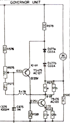
Looking at the governor circuit of the 533, the design is actually similar:
View attachment 76915
Assuming you have replaced the AC127 and AC128 with a similar metal cap germanium pair, I would suggest that you retest them (continuity/diode setting on the multimeter) outside of the circuit. You should not get any voltage flow from collector to emitter and vice versa as if you do, the transistor may be leaky. Even un-used germaniums may turn leaky while in storage. Also check the CD2A diodes and resistor R580 (1.2K) as if this resistor's value drops, the motor will speed up. That little choke (coil) should also be checked. It should not be open or shorted). Also check the capacitance of C675 1mfd, especially the polarity (this is a germanium circuit and the (+) rail is ground. Also run voltage checks across the collector, emitter and base of both transistors and you should get readings very close to what is mentioned in the circuit diagram. The next check would be to measure the voltage across the power rails (across the 1000mfd filter capacitor and compare the voltage across the motor. This is a 12v circuit when operated via AC mains and 9v circuit when operating on batteries. I recollect my Philips radio recorder worked on 9 volts when powered via AC mains, and on 7.5 volts when batteries were used. The cassette recorder featured a 5v motor and the speed controller circuit provided it with 5 volts irrespective of whether 9v or 7.5v came from the power supply. So coming to your 533, if you check the voltages across the motor, it definitely should not be 12v and you should get reduced or increased readings when you turn the preset. I suspect your record player has a 6v or 5v motor. Its a simple circuit and should definitely be able to get it to work.


