DEFECTING,........ from Digital .............back to TUBE / ANALOGUE / LPs

Status
Not open for further replies.

drlowmu

Banned
Banned
Joined
Oct 28, 2020
Messages
721
Points
93
Location
Warrensburg, Missouri
For the last eight years, I have done digital with Pioneer's top-of-the-line-then, 31 pound, BPD-09FD Blu Ray player. I never trusted digital, the whole concept of it, makes me question it's validity.

My first audio Mentor, the brilliant Robert W. Fulton had it right, in my opinion, when he was living in the 1980s. He would say this privately to me " All the King's Horses, and all the King's Men, could never put poor Humpty together again ".

So, I never went for streaming, high resolution digital servers, DACs, etc. etc. etc. Nope, not a penny did I, or would I spend. And when ever I bought a CD, I always felt I was starting-out with something intrinsically inferior, VS: .......... my L.Ps in Analogue.

I owned a solid state Phono - Line preamplifier, called a " Bravura ", which did a reasonable job, especially considering it was old and used early ICs. But I always yearned for a top-notch tube Phono stage, to do RIAA EQing. The Bravura, decades old, had its share of " down time" and I am a solid state / E.E. dummy, so I could not ever repair and maintain it on my own.

Last week, I finally started DIYing a TUBE RIAA EQ project, something I could understand, repair, modify to the " Nth " degree, all on my own.

There were two existing designs that held my interest. For Phono RIAA EQ, I personally was ONLY interested in using 12AX7s !!!!

For the last three years, I have revised Jim Hagerman's Coronet Two circuit, to use his passive EQ, in an a no-holds-barred from-scratch design and build. It was to employ with my own favorite audio and power supply implementations, such as double Shunting the B+ supplies and using Dennis Fraker Final Filters, to separately feed each tube's Plate resistor it's B+.

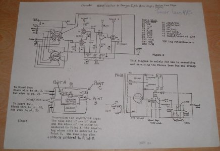
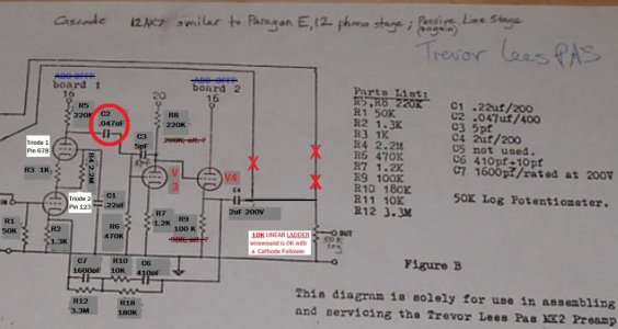
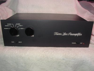
The second 12AX7 circuit was the Cascode RIAA EQ, as found in the rare and sought-after Paragon E and almost verbatim in the 1970s Trevor Lees ( Australia ) Dynaco PAS-based preamp mod.

I have a good audio / personal friend since 1979, local to me, who had THREE Trevor Lee's ( Dyna / PAS mod ) preamps stashed away. He gave me permission last week, to " go at it "...... and treat one unit as though it was my own. Apply any and all ideas I had, as of 2023 !!!

I will use THIS thread, to document how I will go about DIYing this Cascode RIAA EQ circuit, to see what I can develop. All the above serves as an initial background explanation, for what ever follows in this thread. Much I'll do is " my own bag " and is experimental, with results not fully known to me presently !!

I am happy to answer any questions.

Jeff
006.JPG
 
Last edited:
what turntable/Tonearm/cartridge will you use Jeff ?
 
what turntable/Tonearm/cartridge will you use Jeff ?
The same basic set-up I used - when Mr. Fulton was alive.

A Spanish KM Audio Linear belt drive turntable, with the larger " European " double thickness / weight platter. A Fulton " Kinetic Barrier " turntable mat with index mark cut into it.

The cartridge is Mr. Yoshio Matsudaira-designed and Entre-made, distributed by Soltear Acoustics. An Entre-1 Fulton-branded moving coil with a conical tip, and a tapered aluminum cantilever. I have 13 of those cartridges left, as I seem to recall.

The tone arm is a USA-made copy of the early SYRINX ( British / Scott Strachan ) tonearm, their PU1 model. It's bearings were later- modified by my friend ( UAL 747 Pilot, now retired, Tom ) to deluxe all-ceramic bearings, and Tom's specially chosen new tone arm wire.

The step up device is also an Entre unit from that era. I forgot the model number. It was Entre's then deluxe version. On the outside, all I can see denoted, on the front and back, is " SUPER HIGH-QUALITY TRANSFORMER ", with NO !!! ET-200 model number.

My interconnects are also Fulton - sourced, and in one span, we cut them in cut down to half a 57 1/8th inch length.
 
Last edited:
  • Like
Reactions: arj
700x470
1306679517121.jpg

These ones ?

Entre is an interesting choice Japanese I believe and the same guy who owns My Sonic labs who makes pretty high end cartridges !
Is it this one ?
IMG-3514.thumb.JPG.177a7f1467bddd4b9f9215a187da6b71.JPG
 
700x470
1306679517121.jpg

These ones ?

Entre is an interesting choice Japanese I believe and the same guy who owns My Sonic labs who makes pretty high end cartridges !
Yes, That is the table but without those five pods. A THICK aluminum platter, flat, with a " Kinetic Barrier " Fulton indexed turntable mat on it.

The tonearm you show is a SYRINX PU2, and I used a copy of it's predecessor, the PU1 as made in the USA, likely unauthorized.

The Entre -1 moving coil with a CONICAL tip, was made specially for Mr. Fulton, at his request / insistence.

Here is the history of the designer,....YES, it is as good as it gets !!!


Correct.......... on My Sonic Labs...he, if living, must be in his 90's !!

700x470
1306679517121.jpg

These ones ?

Entre is an interesting choice Japanese I believe and the same guy who owns My Sonic labs who makes pretty high end cartridges !
Is it this one ?
IMG-3514.thumb.JPG.177a7f1467bddd4b9f9215a187da6b71.JPG

That is my step up unit, but before they ever put " Entre" and ET-200 on the rear as we see it. Maybe its all-silver wound. 10 Ohms to 4K. I bet they supplied Mr. Fulton's ET-200 units BLANK - named, and he sent it to customers and me, a rep and personal friend, that way.

That is my step up unit, but before they ever put " Entre" and ET-200 on the rear as we see it. Maybe it is all-silver wound. 10 Ohms to 4K.

I figured it out today !!! I bet they supplied Mr. Fulton's ET-200 units BLANK - named, and Mr. Fulton sent it to customers and me, a rep and personal friend, that way.
 
Last edited:
INITIAL MODIFICATIONS, ............3-30 to 4-3-23

I have had my Trevor Lees unit on loan for a year or so, and I never spent much time using it, in it's stock form. It was decent, but not good enough to hold my interest, listening - wise. I needed a higher fidelity presentation, to begin to enjoy it. Since it was on loan, I could not freely mod it to get it where I wanted. I HAD TO EVENTUALLY RETURN IT " STOCK ".

On 3-29, I wrote to my friend who owned the unit, and asked him if I could freely mod it, try to improve it. He is using the same preamp in one of his systems. My friend had THREE of these units, so he told me to " go for it ". He actually suggested studying both of his unused preamps, but modding only ONE, with the idea that I could keep it, long term.

Hooray. Joy. I proceeded on 3-30, with a free hand.

As I listened to some of my reference L.Ps on 3-30-23, I thought, " this is so " murky " sounding, why install new high-quality resistors that cost six or seven dollars each, and have it all connected by what was essentially JUNK for wire ????

Then I recalled what my first Mentor, Mr. Fulton, used to always tell me about wire.


" An inch of bad wire can ruin the musical experience ".


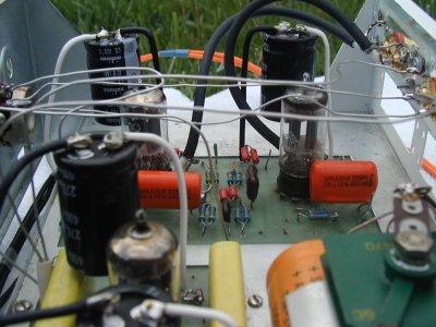
With my uniquely- Mentored audio background, I spent the first four full days, RE-DOING the unit's wiring. Dyna PAS3s were connected with thin solid core copper wire. It used two 1970's Printed Circuit boards, with thin traces . I thought to myself, " this is JUNK ", and asked myself, how can I improve it ??

The first thing I did was replace the main GROUND wire, soldered to the power supply's quad can, to each of the unit's two PC Boards. I wanted maximum wide-band transfer efficiency, so this preamp plays dynamically.

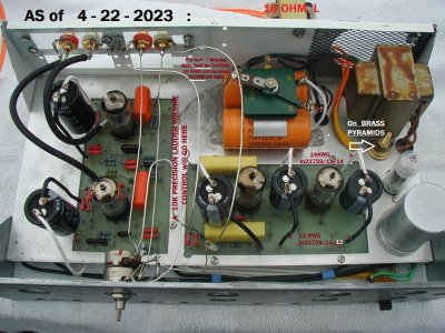
What is the single best wire I know of, that is affordable, and will play wide band with power ?? That is easy, I have told you all about m22759/11/12 wire. Yes, copper stranded, silver plated, teflon coated Mil Spec wire will become my ground connection, PC Boards to Quad Can. 12 AWG has proven to us to be the overall best sounding AWG in that Mil Spec series, to retain a wide band music performance.

Certainly WAY OVERKILL for a preamp drawing 10 milliamperes or less, but I wanted the best wire for myself, for my own use.

Installed were two runs of m22759/11/12, as the long ground leads. Uninstalled were the tiny-AWG solid-core stock Dyna wire.

What about the B+ feed, for the Quad Can to each PC Board ? I decided, in order to maintain high frequency capability, to use 14 AWG, not 12 AWG, to supply the B+ voltages to the boards. M22759/11/14.

This resolved the energy feed, to the PC Boards, Grounds and B+.

Idealized in my mind. Likely, only " I " in audio, would ever make such choices. LOL. An E.E. might theoretically think I was a fool, but is that so ???? I may perhaps enjoy the last laugh !!

So I am feeding the PC Boards as best as I can, transfer - efficiency wise.

What about the PC Boards themselves, connecting all the parts of the audio circuit ??

Question, how good is this 1970s developed PC Board, trace-wise ? Remember " An inch of bad wire " ????


....well wait a moment,...... a PC board trace is NOT WIRE at all. Granted, it makes an electrical connection, and allows for mass production of a circuit, but is it "wire". Of course not !!!


The entire PC board from the 1970s has runs or traces, that are UNACCEPTABLE to "me" ... each board is simply junk, wire-wise. Presently in 2023, traces may be wider and higher quality, but for an audio Phono preamplifier, or amp, ........... Point - to - Point, with ideal wire, reigns supreme sonically !!

- - - - - - - - - - - - - - - - - - - - - - - - - - - - - - - - - - - -

What gets covered next, is what I did to carefully " fix" the PC Boards, and allow them to become performance -wise, musically acceptable.

This deserves a separate post to describe, which will get done when I am fresh. What followed with the PC Boards was amazing to me. One of the best music experiences, and DIY audio-learning experiences, I have ever had !!

Stay tuned please, so I can share this !

Jeff
 
Last edited:
STEP TWO : MINIMIZE the AUDIO MESS - always created .......... by P.C. BOARDS

Step One was to rewire the runs from the power supply to the circuit's P.C. boards. As prior-explained, I settled for 12 gauge ( M22759/11/12 ) for the unit's three main ground wires, ( back to the Quad Can ), and 14 AWG ( M22759/11/14 ) from the Quad Can, feeding B+ voltages to three locations at the P.C. Boards.

Step Two, this post, deals with what was done to get the PC Board improved upon.

As previously written, a PC Board is NOT normally a decent wire for high performance audio use. In fact, a PC Board is not a wire at all. It is a cost effective way to mass produce electronics, and connect parts together so the needed parts function as a given circuit. For audio use, I am afraid it is second best, usually not equal, to tube circuits wired Point to Point !!!! To " put my money where my mouth is ", early on I developed a plan to modify my Trevor Lees PAS MK1 Preamp's PC Boards.

To make this a learning experience, I decided to lay solid core " Wonder Wire ", 19 AWG solid core OVER the traces of the PC board, and carefully solder the Wonder Wire precisely to the traces, following the same exact paths, to avoid any possible " skewing " of the sonics due to unequal wire-path lengths. Michael Percy Audio carries Wonder Wire , $1.75 a foot.

All my testing was done, not with O-Silly-Scopes, but rather 100% by ear using L.P.s. This is a phono preamp. In the end, the goal is to listen to it play back L.P.s,........ so that is how I test it. I rotate 5 L.P.s , as follows :

1) Yellow Bird by Lawrence Welk . Dot Records DLP25389 . an early Randy Wood recording, need I say more ?? A+++.

2) North Park Elementary Choirs, 4th, 5th, 6th Grade Kids . Ark Recording Company / Fulton Records, my 1st Mentor. A.

3) The Big Band Sound of Lawrence Welk. Ranwood Records Inc. Stereo R-8114. Randy Wood again. TOP notch 1973. A+

4) Domenico Scarlatti, Sonaten Fur Cembalo by Gustav Leonhardt . Harmonia Mundi 1C / 065-99 615 EMI-Electrola 1970. A

5) Beethoven "Emperor" Concerto, Arthur Rubinstein w. B.S.O. and Eric Leinsdorf . RCA LSC-2733 Stereo 1964. Sound is C.


A 12AX7 dual triode vacuum tube has several leads needed to operate it on the P.C. Board. A couple of shared heater leads, and for each triode section : a cathode lead, a plate lead, and a control grid lead. I systematically concentrated on laying / soldering Wonder Wire on each lead's span on the P.C. board, and LISTENED to how it effected each lead I'd augmented, with my five L.P. sources. Was it better or worse ? ( Always better !! ) and by how much of a difference, and what precisely was better ???

The preamp's volume control was NOT varied.

I listen when testing, at higher SPLs than average people do.

I spent from 3-31-23 to 4-3-2023, laying wire over the P.C. Board Traces, and evaluating each change. On the first two days, I was DIY " blown away " at the lovely and large changes I heard, in dynamics, tone, definition, and overall listening mental involvement, that the P.C. Board augmentation brought. I learned from doing this LISTENING, a very valuable lesson or two !!

The associated equipment to do this listening was my highly-capable 6005 HFV 2021 stereo Hi Fi amp, running in parallel- mono, and a single ALTEC LANSING A7-8 VOTT ( Voice of the Theatre ) speaker ( 515G-8HP and 802D ) with the HFV 2022 " TRIO " m22759/11 speaker leads. I use just one channel of a stereo source, into one VOTT, to make evaluations easier, and still get a sense of stereo placement and imaging, that is present this way with ALTEC drivers !!

I wish you could have been there, to hear each change over the four days, as I did. P.C. boards are NOT wire !!!

There was done other interesting work on days 5 through 8, ( which is up to today ). That gets covered in a FRESH posting.

Thanks for allowing me to share this P.C. Board FIX experience !!! New to me, and possibly you .

Jeff
 
Last edited:
-------

To make this a learning experience, I decided to lay solid core " Wonder Wire ", 19 AWG solid core OVER the traces of the PC board, and carefully solder the Wonder Wire precisely to the traces, following the same exact paths, to avoid any possible " skewing " of the sonics due to unequal wire-path lengths. Michael Percy Audio carries Wonder Wire , $1.75 a foot.

Wonderful report and log Jeff.

The above is of course possible only in simple circuits with tubes I guess or the main lines for SS devices dealing with power can also be done ?
 
STEP THREE, the next FOUR DAYS , Mk.1 to a Mk.2, ...... PLUS

On 4-03-23 I showed the preamplifier Board Augmentation work to my friend Mark , who gave me the First Trevor Lees phono stage of his to mod - as I wish. He must have liked seeing my Board augmentation. Mark said " Jeff, since I have three of these units, and am only using one, YOU need to take the Second unit, and keep it STOCK as a reference to listen to, to hear if you are going astray in your work."

Great idea, thought I. Mark is cool.

He installed four smooth plate Telefunken 12AX7s in his Second unit ( so all the tubes were the same in both units ) and I was " off to the races ", doing listening comparisons. First however, I looked at the Second unit carefully, and noted it was slightly different, ( more advanced ), than my earlier First unit !!!

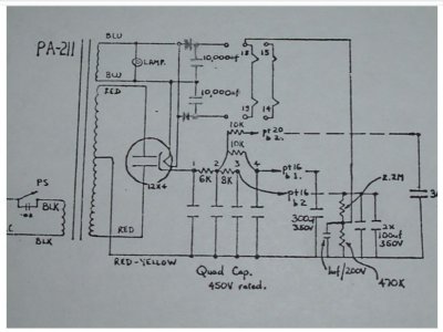
His Second unit had solid state rectification, whereas mine had a 12X4 tube rectifier. His Second unit had two 300 uF B+ supply capacitors, whereas my First unit had just a single cap. These three caps in the two units were all the same - 300 uF at 350 VDC, vintage orange-colored Sprague ATOMS. The Second unit also had a simple voltage divider string, that elevated the Heater Supply above ground.

There is written documentation of the Trevor Lees, which matched the Second unit, ( not my First unit ), except no solid state rectification was shown. The documentation called the phono unit a " Trevor Lees pas MK2 ". ( Mark's Second unit may have been a MK. 3 Version, with no 12X4. ) In any case, I was anxious to hear it, stock. Listening to my reference L.P.s, Mark's MK2 pleasantly surprised me. In a few ways, the stock Second unit was better than my First ( worked upon by me ) unit !!! GOOD to know.


TL 3 of 3.JPG

I immediately decided that my First unit needed to be converted to a MK2 , with a split B+ supply , one B+ node for each Board. It was JUST a 10K resistor off the Quad Can , some 14 AWG Mil Spec wire, and another 300 uF Supply cap, with a separation of the B+ feeds, between Board 1 and 2. ( Remove a between-Boards B+ Jumper Wire ).

TL 1 0f 3 SUPPLY.JPG

Well, as I expected, this splitting of the B+ feeds makes-for a nice listening difference. My First unit became significantly more defined, and detailed, more like the Second unit in many ways, on music playback.

Genuine progress was made, in comparing and making this B+ supply change. High quality resistors ( vintage German Rodersteins ) are on order, to address the voltage divider for the Heaters to be elevated in voltage potential, above ground. That is a week away, parts are not yet shipped.

I have often written in HFV " In the end, we all listen to a music-modulated Power Supply. How good is the Power Supply ". Along these lines, and after being SO PLEASED with splitting the B+ supply ( MK1 to MK2 ) I came up with an original idea for yet another Power Supply " split " .

Board #1 contains the Input Cascode stage , two 12AX7s, one for each channel. I decided to split / separate their common / shared B+ feed. Adding yet another 10K resistor from the Quad Can, some 14 AWG m22759/11/14 wire, and a 300 uF Capacitor bank, and " breaking " the P.C. Board 1's common B+ run, we can gain a separate Cascode B+ supply - for each channel. No longer shared Left to Right !!!!

On Days 6 and 7, I did this. Since I now for testing listen in MONO, I will have to wait until listening in stereo, to fully appreciate what a mono B+ supply for each Cascode Input stage does. Common sense tells me it was a smart change to make. There is no way to A-B it presently, however. I am pleased I thought of and actually executed it - this B+ circuit refinement.

My First unit in seven days, has gone from a single shared B+ supply, to a MK2 double / split supply as per the schematic, and finally ........ to Jeff's triple-split supply as of 4-7-23.

New first-time-ever-heard nuances to RCA's 1959 " Harry Belefonte at Carnegie Hall ", his voice, the trumpets, were a JOY to hear / experience.

DIY rocks !!

Jeff
 
Last edited:
I forgot to mention, on Day 8, Friday 4-07-23, also modded was the Power Transformer's mounting inside the First unit.

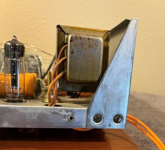
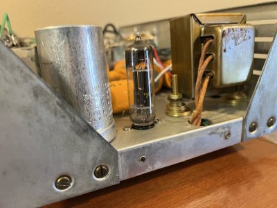
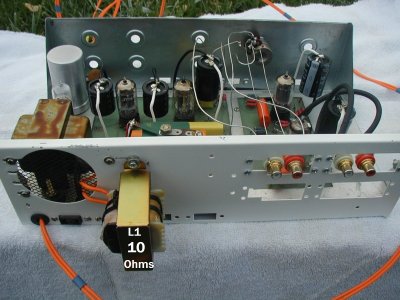
The PA-211 Power Transformer was newly mounted 1/2 of an inch above the audio chassis, using all brass ( non magnetic ) hardware.

This does multiple good things :


(1) The nasty fields surrounding the Power Transformer do not feed as intensely - into the steel audio chassis.

2) The transformer, made as economically as possible by DYNA, gets better airflow and cooling from its underside, now elevated, and

(3) the pyramid-shape non magnetic brass spacers dissipates vibration - effecting less the chassis, tube elements and audio circuitry.


One elevates with a pyramid shaped spacer - all brass, with the " point " of the pyramid touching the bottom of the transformer mounting tab. I actually used #8 brass hardware , as follows : (2) 1 1/4 inch brass 8-32 bolts, and to get the 1/2 inch spacing , three different sized brass washers. (2) washers at 5/16" O.D., (4) washers at 1/4 " O.D., and (4) #8 brass washers. I use (1) #8 brass lock washer and (1) #8 brass nut, tightly forming a rigid all-brass pyramid mount.

I learned this technique from my wonderful audio Mentor, audiophile Dennis Fraker of Serious Stereo. He developed this technique and has used it successfully, for many years now.

Jeff
 
Last edited:
INTERESTING LISTENING EXPERIENCE ... on 4-10-23 !!!

I just finally listened today, after changing two things at once, ( 1 ) new Heater Supply Caps and ( 2 ) the prior post mentioned....- the existing PAS Power Transformer's all-brass "PYRAMID MOUNTING ".

I therefore can not ascribe which change created which result, but if I had to guess, I'd say the brass pyramid mounting likely was 3 out of 4 in probability as to the change in what I just heard.

The playback on every L.P. of the five reference L.P.s is slightly BETTER !!!

It shows up MOST on my worst -recorded RCA Beethoven Symphonic L.P., the Emperor piano concerto. :)

The musical entries of all the musical sections of the orchestra, violins, cellos, brass, tympani, is more distinct and realistic, VS before !!!

Additionally, EVERY struck note on the piano sounds " more real / more believable ", to my senses. Each struck piano note became " more complete " in play back, and distinct from the symphony entries. Symphonic entries by the orchestra sections themselves, and with the piano, are more concise, less blurred.

LOL, only here, first and NOW on HFV will anyone ever read this on line - put in writing.

The all-brass Power Transformer Pyramid mounting conversion cost me $14.41 USD at my local " ACE " Hardware store.

On my SE DC Power Amps, I always did brass pyramids " on faith " as a suggestion from my audio Mentor, Dennis Fraker.

Only he and I do this - to my best knowledge, in ALL of our audio world !

I have been doing this on my SE DC amps, since 2007, but have NEVER A-Bed this........ until two hours ago.

I am very impressed with what I just heard. MOST PEOPLE likely dismissed, " phoo phoo it " when I wrote this up - very specifically - this technique, just one post above !!!

All I can tell you is hearing is believing, and I am mentally sold on this for the rest of my life.

Brass bolts , 3 different brass washer ODs and a brass nut and lockwasher. You can NOT get this audio performance ANY other way - to my knowledge - my HFV friends.

New quality audio parts should arrive in a couple of days. Ohh boy !

Jeff
 
Last edited:
Whats a pyramid mounting Jeff ? can you share a pic ?
IMG_0233 crop (1).jpgIMG_0224.jpg


On a really good system, this is the best way we have heard to isolate a Power Transformer, over the last several decades of experimenting / listening.

Rigid ALL-brass Pyramid mounting, about 1/2 an inch off the metal chassis, provides enhanced audio performance, that one simply will NOT obtain, ANY other way.

DO you want to hear audio playback as BEST as possible, THIS is a requirement if your system is in other ways, optimal.

Of course, if your gear is conventional, not close to the best possible, what this Mod brings to the table, will not be heard or ever fully realized !!

Jeff
 
Last edited:
STEP FOUR - Install acceptable Resistors :

One can not AURALLY determine what a resistor will sonically do, until the most basic Trevor Lees MK1 PAS encumbrances are resolved, in advance.

To that end, up until now, for the first two weeks, reported on HFV are these MOD steps :

1) improve the Ground and B+ wire
2) apply "real wire" augmenting key Printed Circuit board runs ( " HUGE " )
3) Install quality / low loss RCA input and output jacks,
4) Mount Power Transformer on rigid all brass pyramid standoffs ( SUBTLE, but otherwise not presently obtainable - and VERY NICE )
5) Convert power supply from one B+ supply node....... into three separately-fed R/C B+ nodes ( HUGE )
6) Rewire low level signal wire runs, out-of and into the RCA JACKS, and VOLUME POT ( more MOD work needed here, best wire needs to be used ! )

All these changes have been A-Bed individually / carefully with the five differing reference L.P.s, described earlier in this thread.

Last Wednesday I received replacement metal film resistors. On Thursday, I replaced the some stock resistors with my MOD choice, two closely matched parallel-connected Roderstein MK3 1/3 Watt resistors, for each location.

Discussion : Doubling up, 2 for 1, is an old MODDER's trick. You often get a slightly quieter resistor, and mainly, improved DYNAMICS - that is a joy to hear and almost always improved, using 2 for 1 !!!! It maintains the stage's originally-recorded signal's dynamics.

Costly Jadis audio electronics currently does this " 2 as 1 " , as did a few top-notch USA boutique equipment designers in the 1970s. Audio Research Corp employed this technique. Japanese MODDERS did this also.

Often, but not always, a traditionally trained E.E. will have a hard time considering this, because their indoctrinated theory will preclude them from even listening to such a configuration. So sad, their mental state precludes the achievable excellence that " an E.E.-dummy " just like Jeff can achieve !!! LOL.

Thursday was " change the resistors which are intimate to the triode vacuum tubes operation " day. That means changing Plate,Grid, and Cathode resistors. There are four high gain ( mu of 100 times ) dual-triode 12AX7s in this phono stage preamp, so 4 tubes Xs 2 triode sections Xs 3 triode tube elements is up to 27 places in the circuit where attention is needed !! ( Its a little less in actuality ). Imagine making a resistor change, and listening to sections of five different L.P.s, to discover and confirm, how that one substitution changed the music's playback.

No O-Silly-Scope is used in this MODDING .... that was done by the original circuit designers. What will a same-value RESISTOR change bring to the table ??? That is the determination to be done.

I did the 220K plate resistor to the input stage's cascode 12AX7 first, and it was a real eye opener ( or ear opener ) to experience. Yippee !!! It was mind boggling to think this was just the first resistor of many, and to HEAR its effect on the needed L.P. analogue RIAA playback.

By the end of the day, I was happy, and glad to hear the effect of resistors upon the Plate, Grid, and Cathodes of all eight triode sections COMBINED. But the Trevor Lees still sounded murky and not fully interesting to listen to - to me!! Unsatisfactory, more work needed to be done, to get rid of the preamp's smaller signature - a murky thumbprint.

Friday's all-day MOD work was to remove and replace all the RIAA phono equalization-associated resistors, in each channel of this stereo circuitry.

By the end of the day, the murky sound and thumbprint was largely GONE, and the DYNAMICS, heard on each ( stereo ) pair of resistor, through my ALTEC VOTT horn loaded system, was unlike anything I'd ever experienced.

Note : I changed one resistor location at a time to do this MOD work, for some thought-out reasons :

1) to EDUCATE myself as to what that one circuit's resistor change does to music's playback and ,

2) in case I somehow goofed-up the one change, it would make circuit corrections easily correctable as to WHERE it is wrong !!

Nicely, by late Friday all the resistor changes caused no problems, and yes, Thursday's remaining " slight murkyness " was GONE, and DYNAMICS were even more impressive - " off the wall " so to speak!! Never heard by me that way on any hi fi system. By the end of the day, this preamp was finally resolving music playback to a degree that WAS holding my mental interest. Inner music detail of instruments was getting to be life-like.

My mind was really boggled, thinking and realizing that ..........this was JUST thoughtfully installing resistors, and I have areas such as MODDING capacitors, volume controls, and signal wiring, YET to MOD and to hopefully.......improve playback of L.P. - recorded analogue music !!

Jeff

TL 3 of 3  EDIT 6.jpg
 
Last edited:
A few important points to provide DIYers, when paralleling resistors :

Make use of pairs are close in Ohmic value to EACH OTHER, not necessarily to the schematic's value,..... but to each other's value.

If the Ohmic values differ much from each other, one resistor will audibly BUCK the other, in the circuit. This can create an audible SKEW, a degrade to the overall sound, which does not exist, with a single resistor in that same circuit location.

For example, with the 1% rated resistors, if 2 were required for a certain stereo unit, at the same circuit location in each channel, one would use four but ORDER six pieces. Match to each other, the best two pairs out of the six pieces.
 
4-22-2023 .... Jeff's intended HIGH - Performance VOLUME POT


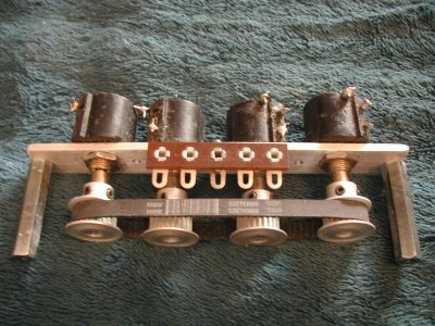
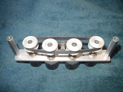
Four individual single three-turn Linear Bourns #3547 10K Precision wirewound Potentiometers, are to be installed, brand new.

All four Precision Pots are to be uniformly-driven by a set of MXL pullies, and a 825 MM outside diameter MXL belt, to become a syncronized stereo "single-knob" LADDER attenuator. It is wired together as a pair of pots - used as a LADDER attenuator for each channel.

Brilliant !!

Both wipers of a pair of pots are connected together, ( with CARDAS' unshielded SILVER solid-core 18 AWG jumper wire. ) Solder it commonly at the CENTER of this wipers'- jumper ) . The Precision Pots' variable wipers'output, - connects to the preamp's RCA output jack's " HOT " connection.

The AC input signals ( ground and hot ), also use Cardas Silver chassis wire, and are connected to separate / opposite ends of each pot.

The other end ( third connection ) of each Precision Pot has no AC input wire ( N/C ), ..... nothing connected to it !

When one pot in increasing in Ohmic value, it's PARTNER Precision Pot is decreasing in value, equally, and ALWAYS advantageously presenting a FIXED constant 10K impedance to the variable circuit !!! A stereo LADDER volume control circuit.


Additionally, if desired : A constant stereo LEFT - RIGHT " BALANCE " adjustment can be made by synchronizing one channel's pot pair, slightly different ( on the 825 MM MXL belt ), as desired from the other channel's ladder pair.

YES, ALL the signal hook-up wire MUST be Silver, 18 or 19 AWG. Quality wise I love uninsulated Cardas solid silver core. Likewise, the RCA jacks themselves, MUST be VERY high quality, for lowest possible signal losses !!

Herein this HFV post, you have been given the design formula for the best possible way I am aware of, to attenuate any line-level music signal, for maximum possible fidelity !! This becomes a fabulous stand alone-system LINE LEVEL attenuator.

The better your system is in transparency, the more telling will be the superiority of this circuit I am disclosing, obtained from my audio Mentor, Dennis Fraker. It employs my own MXL belt-pulley system design, to get all Precision Pots to turn in synchronization . :)

This 10K LADDER will sound superb, installed my RIAA EQ Phono preamp, and driven by the 12AX7 cathode follwer last stage !!!

The incentive EXISTS for me.

I own about 13,000 L.P.s, collected judiciously since my teen years. ' Bought 10 more L.P.s today, on 04-22-23. The newest Cascode 12AX7 preamp modifications - the last three weeks of work shown today, must be about 50 to 60% completed now.

Ladder Assembly 2  of  2.jpg


Excuse above the " sloppy " and or missing terminals. 4 brand new pots will be installed, for my own personal use ! The volume shaft should extend from either end-side of the foursome, for the most efficient interface and MXL belt tracking of all 4. See below :

Ladder Assembly 1  of  2.jpg

This LADDER will be superb installed my RIAA EQ Phono preamp, and driven by the 12AX7 cathode follwer last stage !!!

The incentive EXISTS for me.

I own about 13,000 L.P.s, collected judiciously since my teen years. ' Bought 10 more L.P.s today, on 04-22-23. These newest Cascode 12AX7 preamp modifications - the last three weeks of work, must be about 50 to 60% completed now.

See how fabulous, precision and quality - wise, the data sheet reads !!

chrome-extension://efaidnbmnnnibpcajpcglclefindmkaj/https://www.bourns.com/docs/product-datasheets/3547.pdf

YES, dual section 10K Pots are possible, but NOT readily available to source.

Pay ATTENTION, to posters who readily disclose the underside and insides of their work, the quality - and who have nothing what-so-ever to obscure !

Jeff
 
Last edited:
Resistors....... REACH for the MOON !!! ..... 04-27-2023

So far, I have come to a music LISTENING conclusion, that Paralleled , closely matched resistors, two resistors for each single resistor position - gives the BEST sonic results.

" Doubling - Up " preserves music's DYNAMICS on a top notch tube phono preamp.

On 04-26-23 I received new resistive parts, ( USA - made Caddock TF020 ) resistors which I installed and listened to - in just one sensitive preamp position, ........the input stage's grid-to-ground.

Very Unusual results !!

On five "reference" LP Phonograph records, I could undeniably on music playback hear the new resistor type ( Caddock TF020 ) as being clearly superior in realism to the prior - existing German film caps. The original German Resistors had been installed / " doubled-up " in all the circuitry.

The newly-installed USA-made Caddock TF020s are over eight times more costly than what was originally used and photographed two posts above, on 4-18-23.

Clearly, the TFO20 can be heard as superior, but the TF020s yesterday were SINGLY installed, and I was MISSSING-out on DYNAMICS.

My 104.5 dB VOTT horn speakers, ( Altec 515G-8HP and 802D ) were previously heard with German film resistors. The resistors were all doubled up, and realistically and excitingly presented music's playback.

The best ANSWER is to use TWO USA Caddock TFO20s in EACH resistor spot. This will provide the great TF020 sound, but without missing the DYNAMICS and REALISM only OBTAINED by " DOUBLING - up."

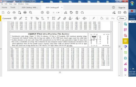
Here is the excellent CADDOCK TF020 resistor description in the Michael Percy Catalogue :

Caddock  Michael Percy Catalogue description.jpg
Jeff
 
Last edited:
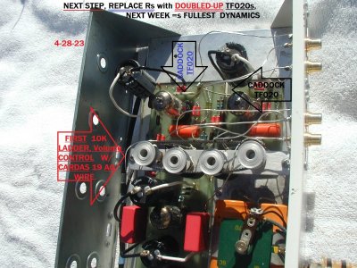
DOUBLE DOUBLE, Toil and Trouble -.............. 04-28-2023

Shakespere

Yes, A Caddock TF020 is very nice to hear, but NEVER equal to two, at double the Ohmic value, in PARALLEL.

DO you like the full DYNAMICS in your phono playback presentation? Once heard, .....I HAVE to have it !!!!!!!

004 REV 2.jpg

Above : Work In Progress.

CADDOCK TF020 Ultra Precision Film Resistor conservatively " nailed " in Michael Percy's 2020 Catalog........... " This is absolutely the most transparent resistor Caddock manufactures and ideal for ultra critical applications where the best possible sound is required. "

In 2023, a TF020 is superceeded as best sounding by the new Audio Note ALL SILVER line of resistors. No, not the Audio Notes with " only " silver leads and end caps. No, they are not equal to Peter's newest ALL silver resistors. $200 USD for one resistor.


Jeff
 
Last edited:
Status
Not open for further replies.
A beautiful, well-constructed speaker with class-leading soundstage, imaging and bass that is fast, deep, and precise.
Back
Top