I have a toppings E50 DAC. It has One Single Ended output (RCA) and two Balanced output on TRS sockets. Somewhere in Nov I made the mistake by inserting TRS jack inside the jack while the DAC is on. POOF the dac went dead. The DAC still showed the sampling rate and the input selected on the front display. I finally decided to dismantle the DAC. Dismantling the DAC was a pain. You have to open DAC by removing two screws on the back panel. After that the back plate slides out with a circuit board with a ribbon cable connected to the front display. If you pull it out there is a risk of damaging the cable. After devicing a strategy, I inserted a long screw driver and managed to disconnect the ribbon cable and the board came out easily. After that using an extender I was able to remove the display by unscrewing 4 hex screws.
Picture 1: Photo of E50 Dac Board with the display connected to it with the Ribbon cable.
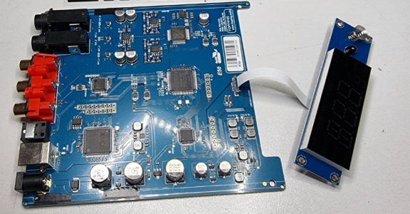
Next thing I did was powered on the dac and connected it to my laptop. The display lighted up but no sound. Using multimer I found that the power supply across the caps is zero volts, but there was power on the DAC chip. Further investigation revealed that this DAC uses SGM3710 is a dual single pole double throw solid state relay designed to operate from a single 2.7v to 12v power supply. It is two normally open (NO) to COM switch and two normally closed (NC) to COM switch. This switch is notoriously susceptible to ESD and is widely known for failed Toppings/Aiyima/SMSL units. I find even the WIIM Ultra uses this switch. This is a Chinese switch and hence details are not easy to get. Lucky for me, because of this issue, there was enough documentation on the web to get details on the SGM3710.
Picture 2: Pin Configuration of SGM3710
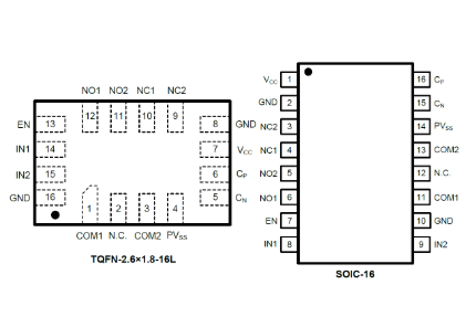
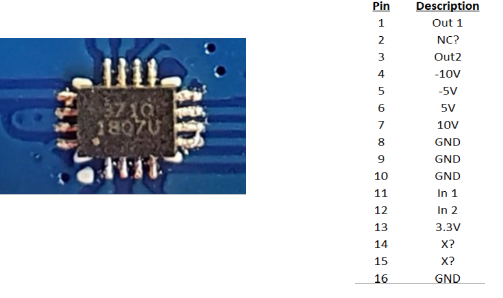
Examining the board I find that D50 uses 3 such SPDT switches. Two for balanced output and one for single ended output. The purpose of the SGM3710 is to act as cutoff and muting switch when the DAC is switched on/off. This avoids the pop sound on the speaker. On the board the SMG3710 is laid out as below. It has audio input connected on PIN 11 and PIN12. The audio output is taken out to the connecttors from PIN 1 and PIN3. Additionally PIN 10 and PIN 9 are connected to ground. So normally the audio output is shorted to the ground. When the SGM3710 is powered it opens the connection from PIN10 to COM1/Out1 and PIN9 to COM2/Out2 and also closes the connection from NO1 to COM1/Out1 and from NO2 to COM2/Out2. Somehow one of the SGM3710 (which switches on the right Balanced output) had shorted and the OP amps were not getting -10v and +10 v supply. So I removed both the SGM3710 for left and right balanced output and using a single copper strand taken from a cat7 cable, I connected pin 12 to pin 1 and pin 11 to pin 3 for both Left and Right balanced output.
Figure 3. Layout of SGM3710 on E50 board.
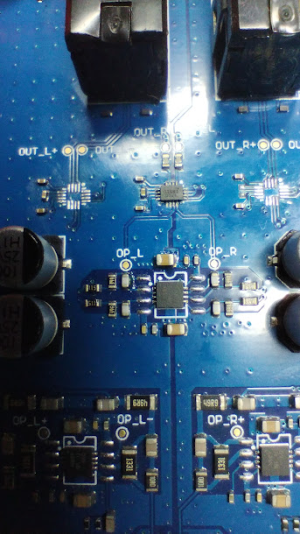
Powered on the E50 and voila the DAC WORKS!!!. This is the photo of the board with two of the SGM3710 removed
Figure 4: Photo with two SGM3710 removed
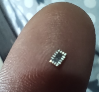
This is the size of the SGM3710 SPDT solid state switch. It took around 2 hours to remove the SGM3710 SMD and solder thin copper strands to connect DAC output to the connectors. Mostly because I no longer have a good eyesight and had to conjure a rig to hold a magnifying glass during the desoldering/soldering process. Probably the most difficult job I have undertaken till now. But two hours well spent.
Figure 5. The infamous SGM3710 switch
Picture 1: Photo of E50 Dac Board with the display connected to it with the Ribbon cable.

Next thing I did was powered on the dac and connected it to my laptop. The display lighted up but no sound. Using multimer I found that the power supply across the caps is zero volts, but there was power on the DAC chip. Further investigation revealed that this DAC uses SGM3710 is a dual single pole double throw solid state relay designed to operate from a single 2.7v to 12v power supply. It is two normally open (NO) to COM switch and two normally closed (NC) to COM switch. This switch is notoriously susceptible to ESD and is widely known for failed Toppings/Aiyima/SMSL units. I find even the WIIM Ultra uses this switch. This is a Chinese switch and hence details are not easy to get. Lucky for me, because of this issue, there was enough documentation on the web to get details on the SGM3710.
Picture 2: Pin Configuration of SGM3710

Examining the board I find that D50 uses 3 such SPDT switches. Two for balanced output and one for single ended output. The purpose of the SGM3710 is to act as cutoff and muting switch when the DAC is switched on/off. This avoids the pop sound on the speaker. On the board the SMG3710 is laid out as below. It has audio input connected on PIN 11 and PIN12. The audio output is taken out to the connecttors from PIN 1 and PIN3. Additionally PIN 10 and PIN 9 are connected to ground. So normally the audio output is shorted to the ground. When the SGM3710 is powered it opens the connection from PIN10 to COM1/Out1 and PIN9 to COM2/Out2 and also closes the connection from NO1 to COM1/Out1 and from NO2 to COM2/Out2. Somehow one of the SGM3710 (which switches on the right Balanced output) had shorted and the OP amps were not getting -10v and +10 v supply. So I removed both the SGM3710 for left and right balanced output and using a single copper strand taken from a cat7 cable, I connected pin 12 to pin 1 and pin 11 to pin 3 for both Left and Right balanced output.
Figure 3. Layout of SGM3710 on E50 board.

Powered on the E50 and voila the DAC WORKS!!!. This is the photo of the board with two of the SGM3710 removed
Figure 4: Photo with two SGM3710 removed

This is the size of the SGM3710 SPDT solid state switch. It took around 2 hours to remove the SGM3710 SMD and solder thin copper strands to connect DAC output to the connectors. Mostly because I no longer have a good eyesight and had to conjure a rig to hold a magnifying glass during the desoldering/soldering process. Probably the most difficult job I have undertaken till now. But two hours well spent.
Figure 5. The infamous SGM3710 switch


