First Tube Amp Build – Guitar Amp Using ECC83 and EL84

santaji

Member
Joined
Jan 29, 2019
Messages
16
Points
13
Location
Bombay
Building a tube amp has been a dream of mine for a couple of years. Earlier this year, I was finally able to start my build which is now complete.

I was on a tight budget, and my main goal was to learn about tube/valve amp construction through this build, and not necessarily build the best possible amplifier. Thus I decided on the AX84 guitar amp circuit found online, more details are available here: http://ax84.rru.com/

Basically, it consists of two preamp stages using one 12AX7/ECC83 and a single-ended output stage using EL84. These being common valves made by BEL is another reason that I decided to go with this circuit. It is based on the vintage tube guitar amps of the '50 and '60s by Fender, Marshall, etc...

Here is the schematic:
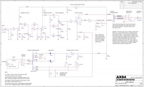
AX84 Circuit.jpg

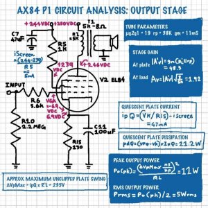
And here are some of my notes on the various stages:
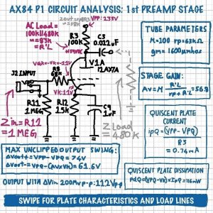


283957630_386004446630826_4899227365092082727_n.jpg

284032861_553052806346457_8986553316059213666_n.jpg

284424745_733895357656641_288141563803276515_n.jpg
285646728_1875113106213064_6279557844555676189_n.jpg

Started the build by fabricating the chassis from 18 gauge sheet-metal. Riveted on the tag strips for point-to-point wiring:
Terminal Strips.jpg

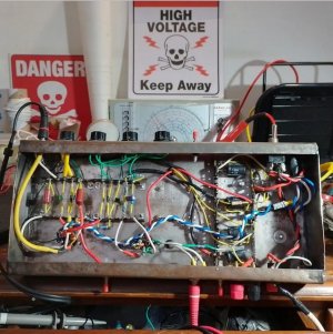
Here is the completed wiring:

Completed Wiring.jpg

And the finished amp: Power and output transformers were salvaged from a junk valve radio chassis.
Completed Amp.jpg

I tested each stage as I built the circuit. More more details on each part of the build, please refer to my 4-part vlog videos on YouTube:

Part 1, chassis fabrication and planning, power supply:

Part 2, filament wiring and power supply updates:

Part 3, wiring the amp stages and some problems with biasing:

Part 4, some tweaks, checking gain and power output, final test:

More pictures of the build and circuit details are available on my Instagram page: instagram.com/_electroidiot
 
Congratulations on your first amplifier build. Your amp, with two stages and SE .......KISS, which I prefer !

May I offer you some critiques, so that you will learn and improve for the future builds ahead of you ?

In a two stage amp, we have found from years of building and careful listening, that a gain of both tubes, when multiplied one by the other, is best designed for a total of 400 times. This 400 provides the most lively and interesting-to-hear long-term music delivery, even though for example, a commonly applied 200 times in a two stage amp would likely " pass a signal OK ". So, when using a mu of 4 2A3, it requires a mu of 100 12AX7 or mu of 100 12BZ7 to have an ideal sounding amplification ( four times one hundred = 400 ) as a two stage amp.

In this guitar amp you have copied, we have a mu of 100 times 12AX7, into a mu of 19 times EL84. That is a gain of 100 Xs 19 or 1,900 times VS the 400 times we find ideal for high end audio . It is over four times too much, and 400 times itself, is already high !!! The EL84 in a two stage amp would sound best with a common mu of 20 times driver tube ( 20 Xs 19 is 380 times, close enough to 400 times ! )

A second topic is your layout. Much thought needs to be applied to one's amp's layout.

Your two row parallel terminal arrangement is sub optimal.

The most critical resistors to the sonics, such as the input tube's plate and cathode resistors ( Ra and Rk ) need to use as short a lead length as possible. In your case, you are applying jumpers from the tube socket to that first terminal strip row, and have placed the resistors between the your two rows of terminal strips.

A better way is to place the Ra and Rk directly, with shortest possible leads, onto the appropriate tube socket pin at one resistor end, and the other lead-end of the resistor - connect it positioned to about where you have your first row of terminal strips.

What you selected as a newbie looks real nice, and I have even seen this in vintage commercial products, but it is electronically sub- optimal. Make sense ?

Also, why not mount your RCA input jack within an inch or so, of the Input tube's grid Pin, and eliminate most of that several inches of Yellow Cable, running under the chassis??? Less signal to degrade, which exists at the lowest signal level of the entire amp !

Jeff
 
Last edited:
Building a tube amp has been a dream of mine for a couple of years. Earlier this year, I was finally able to start my build which is now complete.

I was on a tight budget, and my main goal was to learn about tube/valve amp construction through this build, and not necessarily build the best possible amplifier. Thus I decided on the AX84 guitar amp circuit found online, more details are available here: http://ax84.rru.com/

Basically, it consists of two preamp stages using one 12AX7/ECC83 and a single-ended output stage using EL84. These being common valves made by BEL is another reason that I decided to go with this circuit. It is based on the vintage tube guitar amps of the '50 and '60s by Fender, Marshall, etc...

Here is the schematic:

View attachment 70862

And here are some of my notes on the various stages:
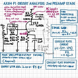


View attachment 70864

View attachment 70865

View attachment 70866
View attachment 70867

Started the build by fabricating the chassis from 18 gauge sheet-metal. Riveted on the tag strips for point-to-point wiring:
View attachment 70868

Here is the completed wiring:

View attachment 70869

And the finished amp: Power and output transformers were salvaged from a junk valve radio chassis.
View attachment 70870

I tested each stage as I built the circuit. More more details on each part of the build, please refer to my 4-part vlog videos on YouTube:

Part 1, chassis fabrication and planning, power supply:

Part 2, filament wiring and power supply updates:

Part 3, wiring the amp stages and some problems with biasing:

Part 4, some tweaks, checking gain and power output, final test:

More pictures of the build and circuit details are available on my Instagram page: instagram.com/_electroidiot
Lovely, congratulations on your build and for the detailed videos. Great stuff!
 
Building a tube amp has been a dream of mine for a couple of years. Earlier this year, I was finally able to start my build which is now complete.

I was on a tight budget, and my main goal was to learn about tube/valve amp construction through this build, and not necessarily build the best possible amplifier. Thus I decided on the AX84 guitar amp circuit found online, more details are available here: http://ax84.rru.com/

Basically, it consists of two preamp stages using one 12AX7/ECC83 and a single-ended output stage using EL84. These being common valves made by BEL is another reason that I decided to go with this circuit. It is based on the vintage tube guitar amps of the '50 and '60s by Fender, Marshall, etc...

Here is the schematic:

View attachment 70862

And here are some of my notes on the various stages:
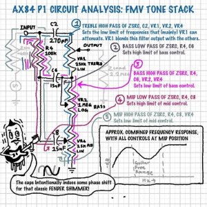


View attachment 70864

View attachment 70865

View attachment 70866
View attachment 70867

Started the build by fabricating the chassis from 18 gauge sheet-metal. Riveted on the tag strips for point-to-point wiring:
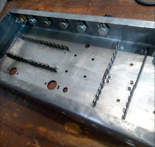
View attachment 70868

Here is the completed wiring:

View attachment 70869

And the finished amp: Power and output transformers were salvaged from a junk valve radio chassis.
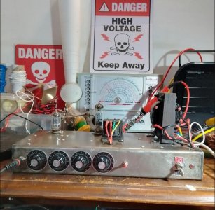
View attachment 70870

I tested each stage as I built the circuit. More more details on each part of the build, please refer to my 4-part vlog videos on YouTube:

Part 1, chassis fabrication and planning, power supply:

Part 2, filament wiring and power supply updates:

Part 3, wiring the amp stages and some problems with biasing:

Part 4, some tweaks, checking gain and power output, final test:

More pictures of the build and circuit details are available on my Instagram page: instagram.com/_electroidiot
Congratulations on your build.

And appreciate your patience to have documented the whole process on videos..

Have to still learn the art of this sort of DIY.
 
To summarize the above totally inappropriate and disgraceful reply.......Congratulations on your first amplifier build. Now let me tell you everything that you did that was wrong.
It's not a nice gesture to directly oblig in this manner. We should appreciate anything what is being taught by a reputed senior member & possibly leave what's non agreed but should never be stopped. I appreciate drlowmu effort in trying to explain possible theory towards a better sounding tube amp.
 
It's not a nice gesture to directly oblig in this manner. We should appreciate anything what is being taught by a reputed senior member & possibly leave what's non agreed but should never be stopped. I appreciate drlowmu effort in trying to explain possible theory towards a better sounding tube amp.

Thanks, YES !!! Well expressed.

The information I divulged on 400 times in a two stage amp is right on the money. It has NEVER been in print, on line, except for my HFV post above. Four hundred times comes from years of DIY build experimentation, and amplifier listening. It is one unknown but key factor which makes a tube amp I might design - truly FUN to hear long term.

The other two comments on keeping the Input tube's RCA Jack wiring as short as possible, and the Input tube's Ra and Rk resistor ends connected directly to the tube socket pins, were each obvious lay-out errors, begging for recognition and a better implementation.

If I only quoted " ATTA BOY, LOOKS nice", the builder ( and some HFV builders ) will never learn how to improve, their next build. :)

Jeff
 
Last edited:
Congratulations on your first amplifier build. Your amp, with two stages and SE .......KISS, which I prefer !

May I offer you some critiques, so that you will learn and improve for the future builds ahead of you ?

In a two stage amp, we have found from years of building and careful listening, that a gain of both tubes, when multiplied one by the other, is best designed for a total of 400 times. This 400 provides the most lively and interesting-to-hear long-term music delivery, even though for example, a commonly applied 200 times in a two stage amp would likely " pass a signal OK ". So, when using a mu of 4 2A3, it requires a mu of 100 12AX7 or mu of 100 12BZ7 to have an ideal sounding amplification ( four times one hundred = 400 ) as a two stage amp.

In this guitar amp you have copied, we have a mu of 100 times 12AX7, into a mu of 19 times EL84. That is a gain of 100 Xs 19 or 1,900 times VS the 400 times we find ideal for high end audio . It is over four times too much, and 400 times itself, is already high !!! The EL84 in a two stage amp would sound best with a common mu of 20 times driver tube ( 20 Xs 19 is 380 times, close enough to 400 times ! )

A second topic is your layout. Much thought needs to be applied to one's amp's layout.

Your two row parallel terminal arrangement is sub optimal.

The most critical resistors to the sonics, such as the input tube's plate and cathode resistors ( Ra and Rk ) need to use as short a lead length as possible. In your case, you are applying jumpers from the tube socket to that first terminal strip row, and have placed the resistors between the your two rows of terminal strips.

A better way is to place the Ra and Rk directly, with shortest possible leads, onto the appropriate tube socket pin at one resistor end, and the other lead-end of the resistor - connect it positioned to about where you have your first row of terminal strips.

What you selected as a newbie looks real nice, and I have even seen this in vintage commercial products, but it is electronically sub- optimal. Make sense ?

Also, why not mount your RCA input jack within an inch or so, of the Input tube's grid Pin, and eliminate most of that several inches of Yellow Cable, running under the chassis??? Less signal to degrade, which exists at the lowest signal level of the entire amp !

Jeff
Thank you for your detailed response. I will look further into each point you mentioned for my next build - hopefully a stereo amp for music listening. But first I will have to build some high efficiency speakers suitable for a low power tube amp.

I do eventually plan on re-doing this guitar amp as well, and I will certainly implement your suggestions about the layout. The circuit I used is based the old Fender guitar amps of the 1950s and 1960s, so I guess the gain is intentionally very high for the classic distorted electric guitar sound.

The information I publicly divulged on HFV in YOUR beginner's thread, was both unique and highly proprietary, as far as amplification factors ( mu ) of two tubes multiplying to 400.

Just yesterday, I looked up the data on " Wammerdyne Heavy ( ????? ) Industries ( ???? ) " 2A3 two stage amp ( direct coupled-good !! ) offering. It costs about $8,000 USD. An E.E.'s " tour de force" with seldom-seen complex solid state B+ regulation, fixed bias, DC filament excitation, etc .


But what the designer did not know, and any subsequent user has to put up with, is sonic sub optimization IME.

A BORING amp to listen to. Mentally un-stimulating over the long term. WHY? WHY ? WHY ?

Easy, simple to ascertain. The Driver tube is touted as a 6922 or 6DJ8 ( Mu of 33 ) and the 2A3 used is my #1 favorite , a JJ 2A3 - 40 !!! ( mu of 4 ).

No inherent " jump factor " can exist !!!!!! That is the formula for long term boredom. 33 times 4 is ONLY 132, far far away from the 400, proven to be decent since 1947.

It is akin to creating the world's most perfect looking woman, beautiful at first glance, but she is sadly missing important internal key organs !!

Amps need to be mentally involving to hear, long term, over years, decades. Reliable also.

Jeff
 
Last edited:
One idea, many possibilities exist :


Another idea :


Many others exist !!! You will not be able to get 20 Watts of what you are calling clean sound, that is also reliable, from P-P EL84s. Do not worry about obtaining 20 Watts .

I personally am ONLY attracted to this design, which, among other things, advantageously has NO GLOBAL NFB loop to detract from the music's sound and timing . Notice the description " unexpectedly good ". NOT unexpected to me !!


The schematic :


My changes : eliminate those two 300 Ohm " grid stopper " resistors, not needed. Bypass the 1kuF electrolytic across the 400 Ohm EL84 shared cathode resistor, with a good quality, small value film cap. For the KEY resistors, see Michael Percy. The 400 Ohm is a Mills MRA-12 @ 401 Ohms. The three 30Ks in each channel is also Mills, a 2 Watt MR-200-8 @ 30.1K. You will flip -out when you hear what these do !!! Rest of the resistors order from the Roederstein columns from Percy. Have fun DIYing and esecially ........ LISTENING to this configuration.
Jeff
 
Last edited:
Hi. I want to make a power amplifier for the guitar that is up to 20 watts. to have only volume (ie to be clean). basically to have for pre-amplification 1 or 2 ecc83 - ecc81 and for output to have 2 el84 (push pull). the rectifier will be made of diodes so we are talking about class AB ,, I just do not find any schematic on the internet.. somebody helps me.

Not versed in instrument amps, but recalled the AX84 project as very active/popular years ago. Seems it's dead as a site, but there are apparently kit offerings and such by a few people. FWIW, I found you this pp6v6 in the Wayback.
 
A beautiful, well-constructed speaker with class-leading soundstage, imaging and bass that is fast, deep, and precise.
Back
Top