Group Buy: Mauro Penasa MyRef Rev C kit

Status
Not open for further replies.
Finally boxed everything up and everything seems fine started up for an overnight burning. The bass n treble seem fine but the midrange seems slightly veiled. Hope linuxguru finds the 100pF mod equally better to the 22pf at C34.
 
... the midrange seems slightly veiled. Hope linuxguru finds the 100pF mod equally better to the 22pf at C34.

Hmm - the usual issue with all MyRefs is that the midrange is too bright until burn-in. Not sure why yours sounds veiled - it could be the large PSU caps (Nover?). Also try the TI LM318P opamps that were latching up earlier, they tend to be a bit more full-bodied in the mids.

I'm now testing one pair of boards with C34=47pF with no latch-up - it may be a reasonable tradeoff between 22pf (lower distortion, but possibility of latch-up) and 100pF (slightly higher distortion, but very stable and free from latch-up).

I got mine boxed in the same 8Audio cabinet, and ordered another one also. The speaker binding posts as well as the RCAs have superb finish and quality. I also a found a suitable 10k dual-gang Philips potentiometer locally that fits perfectly, but the shaft seems to be 3.5mm, while the 8Audio knob is for 5 or 6 mm shafts. I solved that by using a plastic adapter sleeve between the 3.5 mm pot shaft and the knob.

One thing left to do is to get an R-Core from Electro-Magnetic Devices in Hyd'bad. Shilchar seems to be another option for an R-core.

Edit: I'm using an LF01/LM318M Class-A hybrid module instead of the plain DIP-8 LM318, and the LF01 tends to have warmer sonics (greater even harmonics) which works well to complement the slightly higher THD20 of Rev E. Since the higher distortion is almost fully H2 with the LF01, the ear doesn't notice it.
 
Last edited:
8audio ones are good and cheaper than those available in india. I have two of them.

The MyRef that I built is housed in this:

Full Aluminium Audio Power Amplifier Case Amp Enclosure | eBay

While I have made the Pass B1 in the same enclosure to form a pre power pair. Can I DC couple the My Ref with the Pass B1.

Do post some pics of your build. Had you told me would have bought one more enclosure from 8audio.

Tested both the texas instruments and NS LM318. My system tends to be more stable on the NS ones.

Loaded my FLAC collection to my laptop. There is no veil in the midrange rather it is crisp as commented by linuxguru. Since I only had a few compressed test tracks that were running yesterday the problem was in the low quality test material.

900x600px-LL-9320a46d_5.jpeg


900x600px-LL-e82c6ab2_6.jpeg


more pictures of previous and current builds.

http://www.head-fi.org/gallery/album/view/id/131889
 
Last edited:
What is instantly evident is the slam that this amplifier has although I still love the mids of the Norge. The midrange of the MyRef are expected to sweeten up after some burn in.

This is how linuxguru describes the sonics of MyRef Rev E and I agree with him:

1. Has an immersive, forward and palpable soundstage;
2. Has explosive and percussive mid-bass dynamics;
3. Is slightly more edgy (less smooth) in the upper mids (but this can be eliminated by using the LF01 Class-A hybrid/discrete opamp instead of the LM318).
 
Last edited:
8audio ones are good and cheaper than those available in india. I have two of them.

The MyRef that I built is housed in this:

Full Aluminium Audio Power Amplifier Case Amp Enclosure | eBay

While I have made the Pass B1 in the same enclosure to form a pre power pair. Can I DC couple the My Ref with the Pass B1.

Do post some pics of your build. Had you told me would have bought one more enclosure from 8audio.

Kudos - you've used the available space in that case superbly and neatly. I saw that case also on EBay, but I figured that it would not be tall enough to accomodate an EI core or R-core trafo easily, so I went with the 8Audio cases that you have below it.

DC coupling: It's not advisable unless the output offset from the pre- and/or source is zero. Typically, unless you're sure that the source has output coupling capacitors and confirmed output DC offset of zero, it's not worth risking it - you may end up cooking an expensive woofer.

Pics: I'll post them shortly - at the moment, the heatsink is resting loose on the floor-plate of the case, and I don't want to risk drilling into that beautiful case just to be able to secure the heatsink.

Source quality: The MyRef is very revealing about the shortcomings of the source material - low bit-rate MP3s are often unlistenable, and even high bit-rate MP3s can be fatiguing. You'll definitely need .wavs or flacs, and the source should have been mastered well with high dynamic range, not an automotive-style compressed hip-hop CD.
 
Last edited:
Yes it was a tight fit. I had to order a 24-0-24 160VA toroid with a height of 50 mm as the casing is only 54 mm high.

Regarding drilling of the base plate you will have to drill some holes and attach the heatsinks to the base with some heatsink compound so the baseplate will act as addition heatsink..

A cleaner mounting option is to use a perforated plate to mount the PCBs on then attach the same to the base plate using double sided tape / adhesive. This way you don't need to drill holes. However the toroid / R-cores will need a hole for mounting.
 
Looks great.

I upload to my Head Fi Gallary and post their links here so they can be visualized here. No everyone is a DIYaudio member and pictures are only available to members.

Fortunately you have received a cabinet from the previous batch (thicker front panel).

You have used a different version of the PCB.I also noticed few changes that what I have:

1. Capacitor at C22 instead of C4.
2. Different DC blocking Capacitor C13.
3. Larger capacitor at C9 (which has a great influence on sound ?Blackgate ?Nichicon)
4. Different high end resistors.
5. A diode adjacent to R11.

How does it sound. Waiting for my upgrades!
 
Head-Fi: OK, I'll check it out.

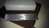
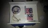
The PCB is the previous version (V1.3). V1.4 is more convenient in most respects, and it uses a functionally equivalent schematic, though some parts have been moved around a bit, and some caps have additional bypasses in V1.4.

I use this pair of boards for testing, etc., since it's known to be stable and the caps (Nichicon Muse KZ at C1, C2 and C9; Black Gate PK at C6 and C11; and Elna LP5 at C3 and C8) have already run in for a while. I'll replace these V1.3 with V1.4 boards with a premium BoM eventually.

The Muse KZs are very good at any location - almost as good as Black Gate STD, but with shorter run-in time. Some of the resistors on this board are black Holco MFRs, which are extremely stable with temperature (i.e. low drift), but a bit analytical sounding (which doesn't hurt the Howland current pump section).
 
It has been more than an year since I bought the MyRef Kit. I was able to spend lot of time during the year end vacation on the assembly. Finally populated the PCB with the components.
Heat Sink: Bought it from Qualitek(Rajajinagar) for Rs.500 (I think it is expensive).
Enclosure: I was looking for different options, but finally found a couple of places in Rajajinagar industrial area where they do the sheet metal work for individual orders. It did cost me 1600(sheet metal job + powder coating), I think it is a bit expensive. It was done using 1.2mm MS sheet and a front aluminum(2mm) plate. They insisted me to be present when they are doing the sheet metal work and it took almost half a day. The enclosure dimension is 17 inch(width) X 4 inch(height) X 13 inch(depth). Got it powder coated with beige color(black color wasnt available that day) with texture finish (
Volume knob: Need to find a decent one, but I think it will be difficult, probably has to settle for some cheap plastic one.

Next step: Need to verify the connections thoroughly and then proceed further.

Thanks,
Hemanth
 

Attachments

  • IMAG0152.jpg
    IMAG0152.jpg
    17.7 KB · Views: 195
  • IMAG0153.jpg
    IMAG0153.jpg
    10.9 KB · Views: 192
  • IMAG0154.jpg
    IMAG0154.jpg
    12.8 KB · Views: 193
  • IMAG0155.jpg
    IMAG0155.jpg
    12.3 KB · Views: 193
  • IMAG0158.jpg
    IMAG0158.jpg
    17.1 KB · Views: 194
Hemanth - it looks fine, though black may have been better. The potentiometer hole on the aluminium face-plate as well as the steel case looks small - you might have to enlarge it a bit with a drill. Try using black allen-head fasteners to secure the front panel to the case - these are locally available, manufactured by TVS fasteners.
 
My My Ref Rev E is now running fine had to replace only one suspicious 22K feedback resistor DC offsets of 5.5 -6.5mV on both channels).

Assembled the LF01 with the utmost care one is giving a DC offset of 100mV while the other has much larger offset to the brink of the relay tripping. The capacitor and resistor values are fine. Will reflow the joints tomorrow except the capacitor.

How much DC offset do you get with the LF01s.
 
The 5mV is pretty good for the normal MyRef. I get about 4mV DC offset for RevC.
Looking forward to the LF01 numbers as well.
 
with LF01 2.7mV and -2.9mV

without the LF01 it was 4mv and 20mV(measured when i built it -6 months ago)
 
I have both the LM318s and my DC offset is lower in the texas instrument chips 1-2 mV as compared to national semiconductor ones 5-6 mV.

Will go through the LF01 modules and recheck the boards in the evening. Basically the Rev E is literally very choosy with respect to capacitances and stability than Rev C. Earlier when I used a 22pf capacitance at C32 (lower capacitances being preferred in the original design, the Rev E was totally dead with high DC offsets, had to increase it to 100pF at which the 318 was stable, linuxguru has found 47pf to be stable too).

I believe it is always better to make changes in multiple boards before proceeding with a new revision because statistically better stability can only be achieved if the testing sample is large.

Atleast the amp is singing fine with the LM318s.
 
Last edited:
.
Assembled the LF01 with the utmost care one is giving a DC offset of 100mV while the other has much larger offset to the brink of the relay tripping. The capacitor and resistor values are fine. Will reflow the joints tomorrow except the capacitor.

How much DC offset do you get with the LF01s.

I need to measure it, but it should be in the ballpark of 10-25 mV with the components supplied. Check that the SMD LM318M is correctly seated and soldered. Measure the resistances in-circuit to ensure that they're approximately correct (not open or shorted). Are the transistors inserted in the correct orientation, and at the correct locations?

Q1 = 2sc1845E, Q2 = 2sa733, Q3, Q4 = 2sc1845F.

Check the 1N4148 polarity - cathode should be connected to base of the PNP, i.e. 2sa733. Please post a pic of the assembled LF01 here if possible.
 
Have checked the resistances and transistors, they are fine, and I took the utmost care to built each using a temp controlled smd soldering iron from goot. One using the wima and the other using the film one. Thought that i will remove the wima later.

The boards are stable on both pairs of LM318s (something to celebrate, however at very high volumes can hear some distortion). Also want to add that my speakers are 6 ohms (8 ohms being preferred with a 24-0-24 secondary).

Will post pictures tomorrow was building a DAC and headphone amplifier.
 
The boards are stable on both pairs of LM318s (something to celebrate, however at very high volumes can hear some distortion). Also want to add that my speakers are 6 ohms (8 ohms being preferred with a 24-0-24 secondary).

At high amplitudes, SPiKe protection inside the LM3886 will kick in, especially for loads below 8 ohms when the power rails are higher than +/- 28V. If it sounds like clipping, and happens intermittently at around 1 second intervals, it's probably SpiKe at work.

You may want to check with 8 ohm loads and see if the same distortion is audible at high volumes.
 
Status
Not open for further replies.
For excellent sound that won't break the bank, the 5 Star Award Winning Wharfedale Diamond 12.1 Bookshelf Speakers is the one to consider!
Back
Top