Some of the modding I had done:
First and foremost is to replace the four 330 uF/25V capacitors on the board with something better and higher value. This brought the most improvement as it completely removed the harshness in the stock board.
These four caps are the ones marked "330 25V RVT" as seen on the photo below:

These caps have surface mounted terminal so it is not easy to rock it from side to side while heating it up to remove it. Care must be exercised to avoid peeling off the circuit board trace. Apply only gentle force while heating with soldering iron. To access the terminals of the capacitors you need needle tipped bit on your soldering iron. The space between the capacitor barrel and the board is very less. My regular 25W Soldron tip could not reach the cap terminals. I used a Goot with needle ceramic bit. Replacement capacitor diameter must be 10 mm or less to fit the available space on the board.
Second change one can make is to reduce gain. My boards come with 32 dB of gain. Here's the table from the datasheet showing the values of resistors:

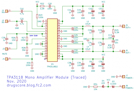
We need to change the values of R1 and R2 given in the circuit diagram. For 32 dB gain in Master Mode, the values of R1 and R2 are 39K and 100K Ohms. Note that the datasheet circuit example uses another set of names for R1 and R2, so it is best to identify them from the nearest pins on the amp chip. On the circuit board (at least mine), R1 and R2 corresponds to R28 and R27. See the first photo in this post for reference. If you remove R27 completely, the table shows that the gain will be 20 dB. This is the easiest path. However, 20 dB gain may be too less for some chains. I preferred 26 dB gain so I removed R28 = 39K and used 20K instead. Later I changed it to 27K for slightly higher gain. Since I don't know where to source SMD resistors, I simply used a regular 1/8W through hole, metal film resistors and soldered them carefully across R28.
Here's a pic of the 10K + 10K resistors in series on the top left corner near the orange capacitor. I didn't have 20K resistor so I had to use two. Later I had changed it to a single 27K:

The blue "drop" capacitor riding piggyback on the orange capacitor is for bootstrap snubber, explained below.
Third mod I did was to fit bootstrap snubbers. These are basically one 330 pF capacitor and a 10 Ohm resistor in series, the 10R being grounded. Check out the diagrams below, borrowed from here:

and the closeup below:

C10, 12, 14, 16 are the bootstrap caps.
C11 and R11 constitutes the snubber for the C10. There is no C11-R11 on the stock board, and that's what we need to install. C11 and C17 are the blue caps visible in the pic above.
Repeat for C12, 14 if you have a stereo board, otherwise ignore them if you have PBTL boards.
So basically for PBTL board you install:
C11-R11 for C10, and C17-R16 for C16.
Here's a diagram on how to implement it practically:

The 10R resistor is grounded on the negative terminal of the 330 uF cap, since the negative terminal of the 330 uF cap is at ground. One end goes to one lead of the 10 uH inductor. These are two convenient points to solder.
Also note that there is a small red line connecting R27 and R28. I use this since the pad of R28 fell off while desoldering.
The last mod is to put a capacitor of sufficiently high value across the DC input terminals - negative terminal of capacitor to negative of DC supply, positive terminal of capacitor to positive of DC supply. I tried 6800 uF/50V. You can safely use anything rated above 35V. This capacitor is supposed to provide some extra energy storage that can help stiffen the power supply line and prevent the power supply from sagging during high dynamic passages. Or at least that's the theory. I have removed this caps since it led to whining noise in one channel. The other is surprisingly dead quiet.
If you plan on the above surgeries, do be careful as the board traces are very thin and break easily.
Hi
I have experimented with snubbers, and in my case the above snubbers does not improve sound. I can hear difference in treble compared to my parallel LM3886 amp, the TPA3118 is more "harsch"/not completely clear. But after doing a lot of investigation on switched amps, I have found that there are two main problems causing distortion on switch amps, supply stability and dead time. Supply stability can be improved as described here by changing the capacitors to something better having lower ESR ratings. But the described snubber design shown does not help on dead time, it only dampens high frequency ringing, if present. On my scope I do not see any severe ringing, at least not in idle mode.
To compensate for the floating output during dead time, I have connected only one snubber between the output filer coils primary side (amplifer outputs). The function of the snubber is to prevent a floating output during dead time, and ideally it should have a large capacitance and very low or no resistance. But this is course not possible, since it would cause the amp go into protection mode due to too high switching current or too high temperature due to power dissipation. But I have now tester R=2,2ohm C=1nF, and it works fine. It really clears up the treble, especially on low to medium volume. The resistor is chosen to limit the switching current, so that it is kept below 15A. The capacitor can be larger, but higher value will cause more power dissipation. 6,8nF would give 2,1W loss in snubber resistor when there is output and 0,2W addition loss in the circuit. Since I only had 1W resistor available the capacitor of 1nF was used.


