Majority PETERHOUSE GRADUATE - Stuck at boot "Welcome" Screen

praveenramavath

New Member
Joined
Mar 13, 2025
Messages
23
Points
1
Location
Asia
Majority PETERHOUSE GRADUATE - Stuck at boot "Welcome" Screen

1741964914246.png


Radio Features: Internet Radio WiFi with Spotify Connect Streaming, Bluetooth, Remote Control, USB Charging and Input, AUX-in, Dual Alarm Clock, Colour Display
More about this Product: See pdf manual (attached with this post)

I am trying to put all the links, YouTube videos I found while troubleshooting to fix the issue so far.

Issue: While starting the radio gets stuck at bar-6 while 12 bars would boot the radio completely to main menu. I am not sure if this is hardware or software issue, though I firmly believe this has to do with firmware (possibly corrupted). I have found a similar issue with another model posted in another forum and surprisingly the model looks very similar to mine including placement of buttons, but I believe Auna 10032916 Silver Star Stereo has AM function antenna included which My Majority PETERHOUSE GRADUATE does not come with, else everything else look strikingly similar.

See: Topic: AUNA SILVER STAR STEREO Freez

URL: https://www.hifivision.com/threads/auna-silver-star-stereo-freez.96193/

While researching online-

I found the below Wi-Fi radios using similar interface software but is customized with the specific model (.bin/binary file firmware might be different) but the overall look and feel is same. Nevertheless, the firmware of these models is most likely not compatible with other models.

  • Lenco DIR 250bk
  • BLAUPUNKT IR10BT
  • SAGEAN WFR-32 WIFI Internet Radio
  • Imperial DABMAN i200
  • Sky Vision DAB 70 IR
  • Inscabin D2/D4 Internet Digital Radio
  • AUDIZIO-Nardo-Internet-DAB-Radio
  • Nardo Internet DAB+ Radio

I also found YouTube video “Imperial DABMAN i200 repair” where firmware is flashed for menu app freeze issues, see below link, looks like the user has used CH-341a chip tp flash the new frimware on this radio.
https://www.youtube.com/watch?v=ZyuZVMpUhKQ

Firmware he used to flash the ROM (bin files) for Imperial DABMAN i200 binary firmware which has similar interface can be found at.
Firmware: https://www.mediasat.com/de/service-center/downloads.html?filterme=112

I am attaching all the ImperialDABMANi200CD bin files in the post just incase if someone later finds them useful to modify and flash it on their respective radio incase they face any firmware issues with their radio.

Majority KINGS DAB+ Internet Radio GIT resources (Have similar software/Interface)
https://gist.github.com/hsiboy/5662ee465979550452cf0470ff144353

Troubleshooting I have done,
  • I tried swapping different 12v adapters and power socket.
  • Reboot with a gap of few hours
  • Try combination of buttons to see if there is a possibility of hard reset
  • There is no physical hard rest button anywhere on the radio
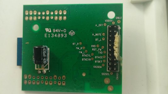
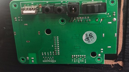
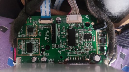
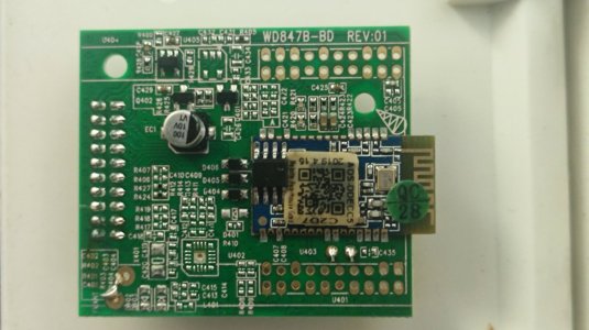
  • Opened the circuit board and cleaned it with WD-40.
But all of them failed. About a month ago it luckily somehow completely booted and I have tried to factory reset from the menu options, it worked well but it rebooted after an hour later and gets stuck again at welcome screen.

If the radio is removed from power for a day and restarted initially it reboots very frequently once every 2 or 3 seconds for about 25 or 50 times before the display stays stable and gets stuck at the 6th bar of the welcome screen.

I tried contacting support but they said they cannot fix it nor give or share any instructions or files to trobleshoot but only consider replacements only if it is in warranty.

Any help is appreciated.
 

Attachments

Last edited:
The main PCB boards and add-on board PCB board(See Image-4 20Pin connector) Sits on top of it (main board) with a single screw.

Image-1 (Main board Front)
PCB Main_F.jpg


Image-2 (Main Board Rear- USB, AUX, Power IN, ON/OFF Switch)
PCB Mani_B.jpg

Image-3 (Add-on board Front)
AB_F.jpg


Image-4 (Add-on board Rear)
AB_R.jpg
 

Attachments

  • AB_R.jpg
    AB_R.jpg
    80.1 KB · Views: 8
  • PCB Mani_B.jpg
    PCB Mani_B.jpg
    108.4 KB · Views: 9
  • PCB Main_F.jpg
    PCB Main_F.jpg
    154.9 KB · Views: 7
  • AB_R.jpg
    AB_R.jpg
    80.8 KB · Views: 7
  • AB_F.jpg
    AB_F.jpg
    124.2 KB · Views: 14
I am actually planning to flash the BIOS. As per Grok, this model has Winbond 25Q32FVSIG or 25Q32 series chip, planning to backup the bin file and reflash it, but if there are any real tech guys with same model radio reading this forum who knows how to use CH341A Programmer, I would sincerely appreciate if they can backup and share their firmware binary with me, so that I can use it to flash my chip.
 
Another useful forum about Auna Silver Star Mini radio model 10032792 (Very similar to Majority Peterhouse Graduate radio ) this website is in polish, someone seems to get the bin file for Auna silver Radio (for stereo and mono radio) I am attaching the same in here (See Auna Silver Star.zip)

Has W25Q32JV 3.3v


From what I understand translating it, the user seems to have similar issue, just a blank screen on start, he seems to flash the bin without luck but when he left the CH341A Programmer connected to computer USB with the other end to the Winbond 25X chip it seems to boot?
 

Attachments

Last edited:
Additing some front panel PCB board images that has the Winbond 25X chip, this is directly connected to the front display LCD with 4 screws, The small PCB on the left of the last 2 pics is the IR receiver for the remote, and the brown board the buttons and volume knob.

The rear PCB pics are already posted earlier in my first post (USB, AUX, Power and ON/OFF switch is directly on the board).


IMG_20250402_214353.jpgIMG_20250402_214401.jpgIMG_20250402_214502.jpgIMG_20250402_214507.jpg
 
Couple of other things I have done so far, I suspected a firmware issue,

- I was initially unable to read the firmware from the original Winbond chip 25Q32JVS1Q soldered on the board, I though I might have burned the chip as I used black CH341A programmer that comes with 5V, so I modified it to 3.3V as per suggestions in youtube and online forums
See : https://wej.k.vu/electronics/ch341a-mini-programmer-fix/

There are also lot of youtube videos you can check on this. See: Volt-modding the CH341a Mini Programmer - LFC#278

Was able to get the CH341A Programmer to 3.3V.

As I said I thought my Original Winbond 25Q32JVS1Q was corrupt but it wasn't althought I used 5V CH341A Programmer, it did not burn it but I was unable to read using SOIC 8 clip (more later). may be I did not properly connect the clip or because CH341a 5V programmer I used before I modified wasn't able to read it... either way, it was unable to read the original Winbond chip so I assumed it was burnt.


Original Winbond 25Q32JVS1Q
1744189504299.png


Here is my modified CH341A Programmer to 3.3V as suggested in online forums/ youtube to read the 3.3V Winbond Chips.
1744189904651.jpeg

CH341A Programmer to 3.3V as suggested to read the 3.3V Winbond Chip.
1744189921345.jpeg

New Winbond W25Q32JVSIQ I bought as replacement for old W25Q32JVS1Q
1744189962711.jpeg

I was able to read and flash New Winbond W25Q32JVSIQ with Auna Silver Star.bin with Neo Programmer and was able to solder it back on the board and when I checked the old Winbond chip which originally came with Majority Peterhouse Graduate firmware to my surprise I was able to read it after I removed it out of the board (So it is not corrupt firmware nor was it burnt when I used the original 5V CH341A Programmer) and when I compared the Auna Silver Star and the Majority Peterhouse Graduate in HxD bin files, both are almost identical except one line. See below.

Only difference between Auna Silver Star and the Majority Peterhouse Graduate bin file (rest is similar).
1744190688353.png
So, I conclude this is not the firmware issue as speculated earlier.

Reading my old W25Q32JVS1Q with CH341A Programmer modified to 3.3V with SOIC 8 Pin Clip
1744191116227.jpeg
 
Last edited:
Hello i have solution for you problem.
plece measere the Pover supply of the processor.
I think it is no 3,3V.
If you need help contact me.
Hi Iliya, Thanks for suggestion. I will check, this is definitely not firmware issue, see my latest update.
 
Hi Iliya, Thanks for suggestion. I will check, this is definitely not firmware issue, see my latest update.
Hello i have solution for you problem.
plece measere the Pover supply of the processor.
I think it is no 3,3V.
If you need help contact me.
I can confirm it is 3.3V, do you have any other suggestions? a friend of mine suspects Nuvoton N32905U3DN (the main SoC)
 
Attaching the Original Majority Peterhouse Graduate bin file here that I downloaded , this was on my chip originally before I flashed Auna Silver Star, I cannot confirm if this is corrupted, but as compared earlier I see very little difference between this and Auna Sliver Star. So very likely this is a working bin.
 

Attachments

Some more image of the radio PCB (Rear and Front and how they are connected including the main processor Nuvoton N32905U3DN)

View from top with rear and front PCB connections. (See image from earlier posts for more closeup shots)
1744268810476.png


Front View (Speakers and PCB)
1744268872803.jpeg

Rear View (Woofer Port hole to the right)
1744268901902.jpeg

Main SOC
1744269040464.jpeg

Newly flashed and Soldered Winbond W25Q32JVSIQ with Auna Silver Star Firmware
1744269109113.jpeg

Rear ports including power-in
1744269272262.jpeg


Below is quick view/ overlook of Auna Silver Star Wifi Radio very identical to Majority Peterhouse Graduate
- (At the end he also opens the rear lid to show the rear PCB)

 
Last edited:
One more observation today, the radio seems to successfully boot when the CH341A Programmer modified to 3.3V with SOIC 8 Pin Clip is connected to the Winbond W25Q32JVSIQ chip and placed in the USB port and powered ON. Radio successfully logged in, but as soon as the clip is removed the radio gets in boot loop cycle. This happened multiple times, so this is exactly the same as observed in the other forum with Auna Silver Star Radio, see the link below.

 
Last edited:
Chat GPT thinks the issue might be with the LDO regulators or buck converters (e.g., AMS1117, MP1584, etc.) that step down voltage from 5V or higher to 3.3V. which if degraded, overheated or under stress might drop voltage below the 3.0–3.3V the flash chip needs.

I found one chip what apperas to be AMS117 on the rear board on the radio. Unfortunately my multimeter is not working at the moment and should get a new one to check the voltage

LDO regulator (See my first image in the #2 post the rear board of the radio to see the location)
1744698472877.jpeg
 
Last edited:
Actual image of my LDO and readings I have observed, correct me if i am wrong but why is input less than the output or have i got the input output pins wrong? There is continuity between the left pin and the middle right both of which are reading 5.0X V
1744995346240.png
I have a very conflicting explanation from Grok, ChatGPT, and claude.ai

Claude:
Given this unusual configuration and the voltage readings from your previous message (3.3V input, 5.04V output), this is further evidence that this component is not functioning as a standard LDO. An LDO cannot produce an output voltage higher than its input voltage.

The component might be:
  1. A boost converter (which can step up voltage)
  2. An incorrectly labeled component
  3. A specialized IC with non-standard pinout
  4. Potentially malfunctioning
The continuity between the back tab and middle pin is definitely unusual for typical three-terminal regulators

Grok:
Input (3.3V) < Output (5.04V): This is not possible for a working LDO.
 
Last edited:
The above looks like a booster converter and not LDO but TPS61221.
The TPS61221 is specifically designed for boosting lower voltages (like your 3.3V) to 5V, making it perfect for the application you observed. It operates in a small SOT-23-5 package as we can see in your image.

Key features of the TPS61221:
  • Input voltage range: 0.7V to 5.5V
  • Fixed 5V output
  • High efficiency (up to 95%)
  • Small SOT-23-5 package
  • 200mA output current capability

Also here is how I found the voltages in Winbond W25Q32JVS1Q while the radio is ON and is in boot loop cycle.
1745002382403.png
 
Last edited:
Actual image of my LDO and readings I have observed, correct me if i am wrong but why is input less than the output or have i got the input output pins wrong? There is continuity between the left pin and the middle right both of which are reading 5.0X V
View attachment 90641
I have a very conflicting explanation from Grok, ChatGPT, and claude.ai

Claude:
Given this unusual configuration and the voltage readings from your previous message (3.3V input, 5.04V output), this is further evidence that this component is not functioning as a standard LDO. An LDO cannot produce an output voltage higher than its input voltage.

The component might be:
  1. A boost converter (which can step up voltage)
  2. An incorrectly labeled component
  3. A specialized IC with non-standard pinout
  4. Potentially malfunctioning
The continuity between the back tab and middle pin is definitely unusual for typical three-terminal regulators

Grok:
Input (3.3V) < Output (5.04V): This is not possible for a working LDO.
TPS61221
Actual image of my LDO and readings I have observed, correct me if i am wrong but why is input less than the output or have i got the input output pins wrong? There is continuity between the left pin and the middle right both of which are reading 5.0X V
View attachment 90641
I have a very conflicting explanation from Grok, ChatGPT, and claude.ai

Claude:
Given this unusual configuration and the voltage readings from your previous message (3.3V input, 5.04V output), this is further evidence that this component is not functioning as a standard LDO. An LDO cannot produce an output voltage higher than its input voltage.

The component might be:
  1. A boost converter (which can step up voltage)
  2. An incorrectly labeled component
  3. A specialized IC with non-standard pinout
  4. Potentially malfunctioning
The continuity between the back tab and middle pin is definitely unusual for typical three-terminal regulators

Grok:
Input (3.3V) < Output (5.04V): This is not possible for a working LDO.
The above looks like a booster converter and not LDO but TPS61221.
The TPS61221 is specifically designed for boosting lower voltages (like your 3.3V) to 5V, making it perfect for the application you observed. It operates in a small SOT-23-5 package as we can see in your image.

Key features of the TPS61221:
  • Input voltage range: 0.7V to 5.5V
  • Fixed 5V output
  • High efficiency (up to 95%)
  • Small SOT-23-5 package
  • 200mA output current capability
 
Chat GPT thinks the issue might be with the LDO regulators or buck converters (e.g., AMS1117, MP1584, etc.) that step down voltage from 5V or higher to 3.3V. which if degraded, overheated or under stress might drop voltage below the 3.0–3.3V the flash chip needs.

I found one chip what apperas to be AMS117 on the rear board on the radio. Unfortunately my multimeter is not working at the moment and should get a new one to check the voltage

LDO regulator (See my first image in the #2 post the rear board of the radio to see the location)
View attachment 90541
Just confirmed analysing the image that is is TPS61221 and not LDO googling the numbers 1852/33 in the image

 
Found these 2 SOTs on the main board there is a direct continuity between W25Q32JVSIQ and top and bottom right pins of what appears to be (SOT-23-5) in the right side. (See some of the images of mainboard with SOC, you should notice them but too small)
1745029314685.png
My plan is to solder a wires directly between 3.3-3.5V output pin and the ground in the above right SOT to Winbond PIN-8 and Pin-4 (Ground) as this would rule out any power rail being noisy or dropping during boot.
1745029384052.png
 
Last edited:
Order your Rega Turntables & Amplifiers from HiFiMART.com - India's reputed online dealer.
Back
Top