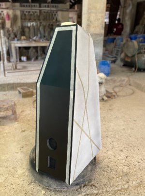
Paul Carmody's Tarkus

Even with my limited experience with horns, I agree. I like even my shorter horns. So can imagine about a larger one.. :)

This is a passive cardioid design. Essentially it is a leaking box containing two 18-inch drivers. Let me copy-paste some pics from Kimmosto's build here.
Here is how the insides of the woofer box looks like. There is just gaps between those wooden pieces on the sides.
View attachment 76662
Now comes the appropriate amount and quality of damping material through which sound from the inside of the cabinet has to pass through to leak to the outsides of the box (as per recent investigations, basotect foam and polyester wool can work well as the damping material).
View attachment 76663

Once sound passes through and reaches outside leaking through the sides, it is appropriately delayed and attenuated (just enough) to create destructive interference from the radiation from the drivers on the front at appropriate off axis directions. Hence the cardioid/supercardioid/hypercardioid pattern forms (remove the leaking box completely, and one gets a figure-8-shaped radiation pattern from the dipole. :) )

Thanks for the explanation. I take it your project is complete?

There is no dsp applied in this design for the cardioid portion?
 
I take it your project is complete?
My current project is complete. But I have already embarked on a new one.. :D
Let's discuss and brainstorm about my current system & upcoming cardioid build experiments here:
I don't want to pollute this thread with information not relevant to this particular Tarkus speaker build anymore
There is no dsp applied in this design for the cardioid portion?
There is no need for DSP to generate the cardioid radiation pattern in Kimmosto's build. It is a passive cardioid implementation. One just needs a leaky box.. :)
 
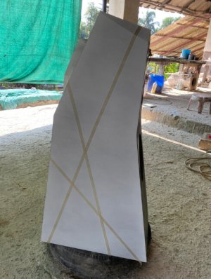
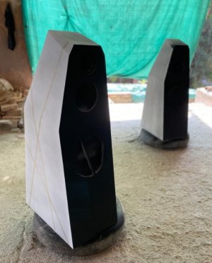
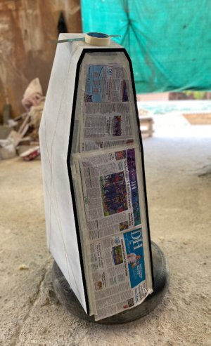
Putty time! said no one excitedly. It only takes a lifetime to finish this process.

View attachment 76658

View attachment 76659

View attachment 76660


View attachment 76661
Let me first commend you on carpentry skills. I'm watching this thread with bated interest. I'm a total noob in these matters. So one question I have is what kind of putty is this? After applying putty, does one use sand paper to polish? How does the finished product look smooth? Is the polishing done by hand or using a electrical think like drill with attachments?
 
Let me first commend you on carpentry skills. I'm watching this thread with bated interest. I'm a total noob in these matters. So one question I have is what kind of putty is this?
Thanks! There are various kinds of application-specific putties available these days, most of which I'm unaware of. They are solvent-based or water-based. Water based are mostly used for indoor applications. I like using solvent-based ones, as they are generally tougher.

After applying putty, does one use sand paper to polish? How does the finished product look smooth? Is the polishing done by hand or using a electrical think like drill with attachments?
The one I used here is a lightweight Polyester Putty, as I already had this leftover from another project. This particular putty is also easier to sand down. I sand down the putty in a criss-cross manner over uneven surfaces before it completely sets with 60-grit sandpaper by hand. This not only evens out the surface but also makes it easy to sand down later. Once the putty completely sets (in about 30mins) I use a random orbital sander with an 80-grit to smoothen the surface. I plan on a matt finish for the paint job, hence limiting the sanding to 80 grit. If you plan on a gloss finish you need multiple passes of sanding over the putty with up to 180-grit.
 
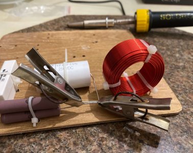
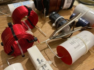
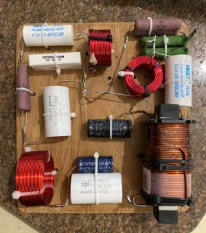
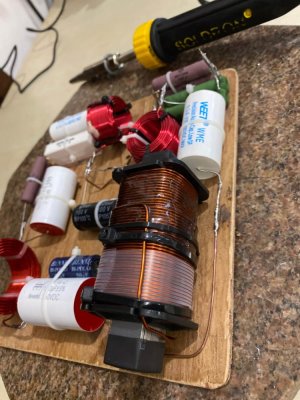
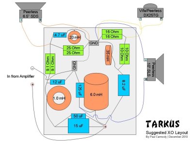
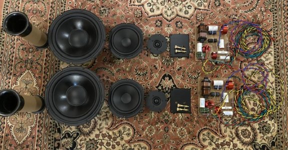
Could someone please help me check if my connections are in accordance with the schematic? If all is ok I can proceed with the next set. thanks.


View attachment 76703
View attachment 76704


View attachment 76705
Wiring and connections LGTM. The only thing are how the inductors with the red enamel are placed on the board. As per the layout diagram those are turned by 90 degrees. I think the placement has been done to minimize EMF generation on nearby components when current flows through these inductors.

The 1.0 mH and 0.20 mH inductors should be vertically placed on the board
The 0.35 mH should be placed horizontally on the board
 
Wiring and connections LGTM. The only thing are how the inductors with the red enamel are placed on the board. As per the layout diagram those are turned by 90 degrees. I think the placement has been done to minimize EMF generation on nearby components when current flows through these inductors.
Thanks for checking the connections!

The reason I had to keep the crossover board compact was so that it could slide through the woofer cavity and then through the bracings.
I had apprehensions about the air coils being close to each other while building this. Then a quick search on YouTube brought up Danny Richie’s tutorial on crossovers. He recommends that if inductors are close to each other then place one vertical and the other horizontal.


The 1.0 mH and 0.20 mH inductors should be vertically placed on the board
The 0.35 mH should be placed horizontally on the board
This should be alright I hope. Looks like Paul has placed them in a way that makes the best use of the board.
 
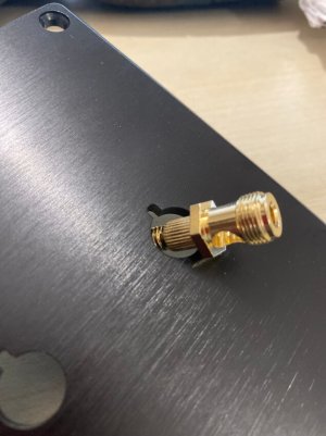
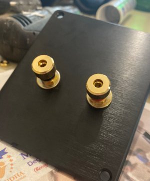
I assumed that the diameter of the binding posts is standard.

IMG_2992.jpeg


Fixed it with a washer in the front and back, sandwiched between gasket tape to make it airtight.

IMG_2995.jpeg
 
Is the Precision Port different from any other flared port? :oops:
Yes; that's what they claim anyways.
The difference will be in the turbulence or chuffing at the ends. Since you are not using [I'm assuming!] a "Precision Port", I suggest that you do all you can to mitigate chuffing at this stage before you glue the port. For starters, using Paul's 13.5" x 4" port size as a baseline, calculate what the correct length should be for a 3" dia. non "precision port".
Also read this: https://drive.google.com/file/d/1SU...avHlbGD2RpKCkjMo3YZTzQv2Pa8qxAzYHle0_BDwhgtGs, and see what you can implement.
 
Last edited:
Wharfedale Linton Heritage Speakers in Walnut finish at a Special Offer Price. BUY now before the price increase.
Back
Top