Simple DIY amp

Kannan_madhu

Well-Known Member
Joined
Jul 29, 2010
Messages
371
Points
63
Location
Thrissur, Keralam
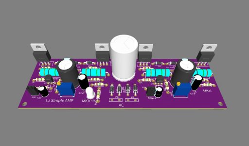
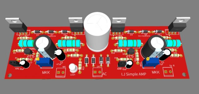
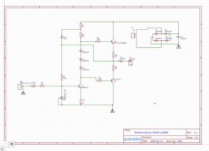
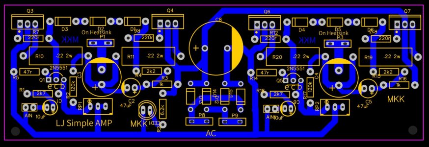
Here is a very simple amplifier circuit by Mr. Joshi Liadel which can be done as a fun project. Very minimalistic design with few parts and it's easy to build on a dotted board. I have made a PCB layout of this (not tested check the connections before you build ) if any one needs it i will upload the pdf files for home etching . this can produce upto 25w
simple amp lj.jpgScreenshot 2023-01-20 105233.jpg
simple 12.jpgScreenshot 2023-01-20 104745.jpg
 
Looks neat and cute. Is this a worth while circuit to build ? Each channel starts with a 10 uF electrolytic, and ends with a 1,000 uF electrolytic, in SERIES with the audio signal, to listen through.
I have not tried it yet but someone who tried told me it sounds good (not in anything Hi-Fi) maybe it has a tone some people like. i posted it here as its a very simple one to build and costs under 300 rupees without a transformer and cabinet.
 
I have not tried it yet but someone who tried told me it sounds good (not in anything Hi-Fi) maybe it has a tone some people like. i posted it here as its a very simple one to build and costs under 300 rupees without a transformer and cabinet.
Generally speaking, the circuit topology of a ten uF electrolytic Input coupling cap, and the 1,000 uF electrolytic Output coupling cap will severely limit the possible fidelity one can obtain in such an audio amplifier design. Knowing fully this in advance, will save the people, who might listen critically, both their time and money.

Your visual work posted is beautiful BTW !!! Admired. Just lovely.

Jeff
 
Looks neat and cute. Is this a worth while circuit to build ? Each channel starts with a 10 uF electrolytic, and ends with a 1,000 uF electrolytic, in SERIES with the audio signal, to listen through.
Its a simple, straightforward circuit... a Bit too straight forward, I'm afraid (despite the bootstrapping by C-2).

A few touches would improve it vastly....

  • A split rail power supply will eliminate the Output Capacitor. (3 dB down at 20 Hz).

  • A preset across the 3 diodes will enable the quiescent current to be adjusted (without adjustments, it would be a bit (too) High 0.55 Amperes... Ideally should be around 0.02 amperes

  • An additional input stage, would raise the input impedance from a rather low approx 5 K ohms to atleast 10K or preferably 20 K ohms

  • The additional input stage would also enable a fixed Gain for the amplifier circuit... Currently it varies with the setting of the 20 K ohms preset.

  • For 25 Watts RMS output the DC Voltage to the Output transistors needs to be atleast 45 Volts DC.

All the above & more can be calculated using ONLY Ohms Law and the formula for Impedance of a capacitor:
X = 1/ (2xPix Freq in Hz x Capacitance in Farads)

If there is an interest, I can run the calculations here.
 
Last edited:
Its a simple, straightforward circuit... a Bit too straight forward, I'm afraid (despite the bootstrapping by C-2).

A few touches would improve it vastly....

  • A split rail power supply will eliminate the Output Capacitor. (3 dB down at 20 Hz).

  • A preset across the 3 diodes will enable the quiescent current to be adjusted (without adjustments, it would be a bit (too) High 0.55 Amperes... Ideally should be around 0.02 amperes

  • An additional input stage, would raise the input impedance from a rather low approx 5 K ohms to atleast 10K or preferably 20 K ohms

  • The additional input stage would also enable a fixed Gain for the amplifier circuit... Currently it varies with the setting of the 20 K ohms preset.

  • For 25 Watts RMS output the DC Voltage to the Output transistors needs to be atleast 45 Volts DC.

All the above & more can be calculated using ONLY Ohms Law and the formula for Impedance of a capacitor:
X = 1/ (2xPix Freq in Hz x Capacitance in Farads)

If there is an interest, I can run the calculations here.
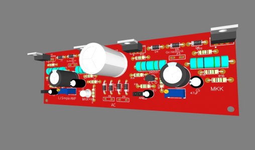
Beautiful !! Just wonderful. Thanks. Build it with good sounding Rs and C's.

Jeff
 
Generally speaking, the circuit topology of a ten uF electrolytic Input coupling cap, and the 1,000 uF electrolytic Output coupling cap will severely limit the possible fidelity one can obtain in such an audio amplifier design. Knowing fully this in advance, will save the people, who might listen critically, both their time and money.

Your visual work posted is beautiful BTW !!! Admired. Just lovely.

Its a simple, straightforward circuit... a Bit too straight forward, I'm afraid (despite the bootstrapping by C-2).

A few touches would improve it vastly....

  • A split rail power supply will eliminate the Output Capacitor. (3 dB down at 20 Hz).

  • A preset across the 3 diodes will enable the quiescent current to be adjusted (without adjustments, it would be a bit (too) High 0.55 Amperes... Ideally should be around 0.02 amperes

  • An additional input stage, would raise the input impedance from a rather low approx 5 K ohms to atleast 10K or preferably 20 K ohms

  • The additional input stage would also enable a fixed Gain for the amplifier circuit... Currently it varies with the setting of the 20 K ohms preset.

  • For 25 Watts RMS output the DC Voltage to the Output transistors needs to be atleast 45 Volts DC.

All the above & more can be calculated using ONLY Ohms Law and the formula for Impedance of a capacitor:
X = 1/ (2xPix Freq in Hz x Capacitance in Farads)

If there is an interest, I can run the calculations here.
  • "A split rail power supply will eliminate the Output Capacitor. (3 dB down at 20 Hz)."
One doubt. how much bandwidth do you expect in the current schematic?
  • An additional input stage, would raise the input impedance from a rather low approx 5 K ohms to at least 10K or preferably 20 K ohms

  • The additional input stage would also enable a fixed Gain for the amplifier circuit... Currently, it varies with the setting of the 20 K ohms preset.
Sure these things will improve it, but the objective of this design was to make a minimalistic amp with minimum components
20 Hz to well beyond 20 KHz: -3dB into 8 Ohms

40 Hz to well beyond 20 KHz: -3dB into 4 Ohms

The Lower freq limit can be halved ( eg reduced from 40 Hz to 20 Hz @ 4 Ohms by doubling the output coupling capacitor from 1,000 mfd to 2,000 mfd.


As they say "Make everything as simple as possible, but not simpler."

The current design is a Great way to explain the basic design principles for an audio power amp, however its not a good enough design to build as a DIY.
 
  • A preset across the 3 diodes will enable the quiescent current to be adjusted (without adjustments, it would be a bit (too) High 0.55 Amperes... Ideally should be around 0.02 amperes

@ IndianEars....could you please explain the quiscent 0.55A calculation; since the outputs are a darlington pair(total 4 Vbe) I was thinking the 3 diodes would hardly turn them on.

Also it seems there is no frequency compensation applied anywhere....if not by design,this should also be added to the list of improvements.
Superb, informative post, sashijoseph. Correct on Both Counts !

1. I missed the fact that TIPs are Power Darlingtons... Yes, they will barely (if at all) turn on.

2. Yes, I did observe the missing frequency compensation - typically between Q-1 base & Collector. I let it pass, since the voltage gain stage will not have a gain in the absence of a current source load... The Collector resistor load is bootstrapped, but I suspect the gain will still be frugal.
Yes, certainly needs to be added on the list of improvements required....

Cheers
 
Above post should have read:

2. Yes, I did observe the missing frequency compensation - typically between Q-1 base & Collector. I let it pass, since the voltage gain stage will not have much of a gain in the absence of a current source load... The Collector resistor load is bootstrapped, but I suspect the gain will still be frugal.
Yes, certainly needs to be added on the list of improvements required....
 
Get the Award Winning Diamond 12.3 Floorstanding Speakers on Special Offer
Back
Top