Where to find Yamaha AVR spares?

OledPhile

Active Member
Joined
Apr 7, 2019
Messages
216
Points
28
Location
Mumbai
Hi,

Recently my Yamaha HTR-2067 AVR went dead. It is missing the click sound and no supply to main transformer. I am suspecting the relay or fuse to be the problem. Where can I buy these spares in Mumbai or online?
 
Hi,

Recently my Yamaha HTR-2067 AVR went dead. It is missing the click sound and no supply to main transformer. I am suspecting the relay or fuse to be the problem. Where can I buy these spares in Mumbai or online?
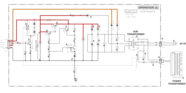
The way these AVR work is that they have a small SMPS as a standby power supply. This is the supply that switches on the main transformer.

Many of these AVR's SMPS are conking of because of the new voltage supply of higher tolerance of 10%. Earlier it was 230 +- 5%. Now it is 240 +- 10%. Power generation equipment with such high lousy tolerance benefits private players in power generation and the guy who supplies electricity to Mumbai is very happy. So voltages can go upto 264 volts. Please don't ever use any electronic equipment manufactured outside without stabilizer.

Most likely it is the SMPS IC which has gone bad. I had the same issue with my avr, which I fixed it myself. But while doing google search I came across a youtube video about a repair shop in Mumbai who fixes these Yamaha AVRs and doesn't charge a bom. Try google search. This is what I had faced with my avr and how I repaired it https://www.hifivision.com/threads/help-required-to-repair-yamaha-avr-rx-v667.86838/
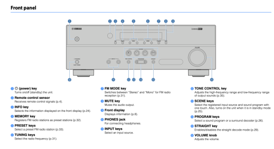
In my case, the unit does not turn on, even in self-diagnostic mode by pressing Info + Tone Control + Power. There is no click sound from the relay whatsoever.

So far, I have verified that the standby voltage is flowing through and even the CPU is receiving it (+3.3M is what it is called on the schematics). S9 has 9+ voltage which is the output from standby power supply. Power button is good and shows continuity when pressed. Main transformer is also showing some resistance so that means it is not open.

What is not working is that the main transformer not getting the AC voltage, that goes through fuse and then relay, that is why I suspect these 2 to be an issue, next when I get time I am going to test these 2. If these 2 are good then it can become a complex matter, but the unit is used very less and I strongly feel the power relay switch to be a problem because in the past I had to press power button couple of times before it would turn on.
Does the red light near the power button glow? The board also has 5v supply to feed the display unit and the circuit that receives IR and button press. Check if the 5v supply is gone. The 3.3 volts is for the microprocessor and the HDMI board. Also a very frequent issue are the two brown colour capacitors from panasonic. These lose capacity as they are in series with the SMPS in the 230 volts line. Most of these Yamaha units have the same SMPS (the board fitted vertically just in front of the power cable inlet). Just be careful with not touching the high voltage section. There will be almost 240 * 1.414 DC voltage which will give a nasty jolt at the minimum. Also check the SMPS IC. In my case it was TOP254 ic which I had replaced. Even the other avrs (Marantz, Denon, etc) are using the same TOP2xx series IC for the standby supply. There will be a small electrolytic cap adjacent to the SMPS ic. This capacitor is highly stressed and known to go bad.

See if you can download the service manual. The service manual will be the most important document as far as voltages and troubleshooting goes. If you have bit of soldering skills, you will be able to repair the AVR.

EDIT: The 9v you mentioned looks strange. It should have been around 5.5 volts or so. Best is to download the service manual and look at the circuit diagram of the video board (Yamaha calls the SMPS board as the video board). I even connected an external 5v supply to switch on the AVR and that managed to switch on my AVR. That's how I came to know that the fault was with the TOP254IC. I never got the same replacement and so fitted another ic TOP258. My avr is now working without any fault ever since. Also I have fitted voltage stabilizers throughout the house.
 
Last edited:
I think it works different in this unit, but I could be wrong. My understanding is the Standby power supply will send 9V to the SMPS, which is then drops the voltage to 3.3 and send it to the DSP board that has CPU and EEPROM. I tallied the voltages based as given on the schematic and they all look fine, what is not working is, once I press power button, the CPU should send a signal to the power relay switch to turn on so power goes to the main transformer, after which the display will also light up, btw there is no standby red light on my unit.

Can you take a look and let me know if my understanding is correct? Service Manual can be downloaded from here - https://elektrotanya.com/yamaha_htr-2067_yht-1810_ns-b20_ns-c20_ns-swp20_sm.pdf/download.html
 
This is the standby supply board. Yes you are correct about the voltage. Are you reading anything on AC detect pin?
1723449003933.png
 
Page 86 and 88 are the important pages. The PWR_RLY comes from the board in page 86. I'm unable to figure out where it is connected. Basically when there is voltage on the PWR_RLY pin, the relay switches on. This is based on the AC_DET supply which goes from the board on page 88 to the board on page 86. I will take a look later.
 
This is the standby supply board. Yes you are correct about the voltage. Are you reading anything on AC detect pin?
View attachment 86000
What does the ACDET do? Any idea?

I thought the power ON signal will come through PWR_RY, I am going to take this board out and short the PWR_RY with S9 to see if the relay clicks, if not then either the fuse or the relay is blown.

I will also check if I am getting 2.97v on the PWR_RY, I think I was getting it but cannot remember now.
 
Page 86 and 88 are the important pages. The PWR_RLY comes from the board in page 86. I'm unable to figure out where it is connected. Basically when there is voltage on the PWR_RLY pin, the relay switches on. This is based on the AC_DET supply which goes from the board on page 88 to the board on page 86. I will take a look later.
If you look at Page 84, the Microprocessor sends PWR_RY signal on pin 49, I am guessing it sends the signal when it receives it from the power switch, and by default when the unit is powered on it may be defaulting to ON. This is why I am more focused on the main power supply board. If 2.97v is reaching PWR_RY at CB151 then for sure something is bad on that board only.
 
Where can I buy these spares in Mumbai or online
Relays and fuse are generally available in any electronic shops like Raj kamal electronics, lamington Rd. I have a dud HTR2064 with NO SOUND / POWER issue, do keep me posted of your further developments. Cinema DSP IC is the usual culprit as per many forums
 
Relays and fuse are generally available in any electronic shops like Raj kamal electronics, lamington Rd. I have a dud HTR2064 with NO SOUND / POWER issue, do keep me posted of your further developments. Cinema DSP IC is the usual culprit as per many forums
Does yours make a click sound on power?
 
What does the ACDET do? Any idea?

I thought the power ON signal will come through PWR_RY, I am going to take this board out and short the PWR_RY with S9 to see if the relay clicks, if not then either the fuse or the relay is blown.

I will also check if I am getting 2.97v on the PWR_RY, I think I was getting it but cannot remember now.
POWER_DET is how the board detects if the supply to the board is coming or not. Don't short with S9. The transistor probably will not tolderate voltages above certain level and will blow with 9v. POWER_DET is for ensuring the board is getting power and when you press the power on button, the board will provide 2.97 volts to the transistor and that will switch on the relay.
 
If 2.97v is reaching PWR_RY at CB151 then for sure something is bad on that board only.
If 2.97v is reaching PWR_RY, then probably the transistor has gone bad. This is the transistor that starts conduing when it receives a bias voltage on the base and then current starts flowing between the collector and emitter
 
If 2.97v is reaching PWR_RY, then probably the transistor has gone bad. This is the transistor that starts conduing when it receives a bias voltage on the base and then current starts flowing between the collector and emitter
you are right, the transistor could also be an issue, I'll make sure to check that as well.
 
you are right, the transistor could also be an issue, I'll make sure to check that as well.
It is very easy to check the relay coil using a multimeter. These relays are robust. What sometimes happens is that the relay gets stuck because of arcing during switch on. Hitting the relay with a screw driver makes the relay unstuck.
 
POWER_DET is how the board detects if the supply to the board is coming or not. Don't short with S9. The transistor probably will not tolderate voltages above certain level and will blow with 9v. POWER_DET is for ensuring the board is getting power and when you press the power on button, the board will provide 2.97 volts to the transistor and that will switch on the relay.
I saw a technician doing this in one of the videos on YouTube and it didn't blow anything, he just checked it briefly to confirm relay is working. May be the transistors can tolerate more volts, it does pass 9V to the relay, relay is rated 9V. Otherwise I will have to feed that power from some other source.
 
It is very easy to check the relay coil using a multimeter. These relays are robust. What sometimes happens is that the relay gets stuck because of arcing during switch on. Hitting the relay with a screw driver makes the relay unstuck.
Let me try this as well.
 
One question, does your standby led lights up red when you connect the power cord. This led glows when you have voltage on POWER_DET pin.
 
Check out our special offers on Stereo Package & Bundles for all budget types.
Back
Top