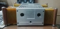
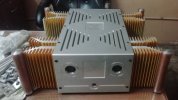
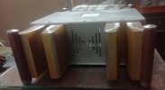
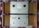
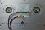
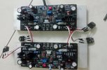
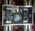
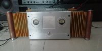
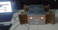
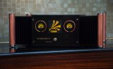
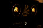
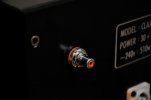
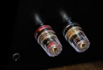
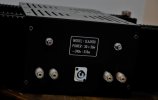
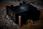
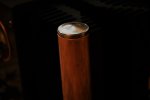
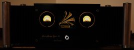
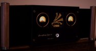
This is the build log of a Jean Hiraga 30W class A amp which is my first attempt to make DIY product without the normal characteristics of a DIY Build. The word DIY usually associates with low cost, functional design with less importance given to aesthetics but I wanted to challenge myself to a design which can compete with professional units in terms of build quality.
I ventured into audio DIY very recently (2018) and was looking for a perfect amp for myself, that was the time I got introduced to Hifivision and stumbled upon this particular thread of Sadik’s. Sadik's JH30.
As most of you know, he is a master craftsman and I always envied his engineering skills. I was a first-time builder neither equipped for such extensive build but didn’t hesitate to grab couple of his pcbs when he listed them for sale in the forum. It was designed by Aniket whos is very well known in DIY space for his DD amps, I didn't have any doubt on the build quality and design of these boards.
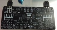
The real challenge was that I had no clue where to start but gained confidence after reading about various JH builds around the world and started ordering parts from RS components. All these were happening in 2019 and there were many others discussing about group building JH in various WhatsApp groups. A friend has asked my help in building one for him during one such casual talk which I tried to discourage as I was not confident myself as a builder. But he was very persistent and had more confidence on me, I didn’t have any choice other than to accept the challenge. We had discussed an estimate and delivery deadline of January 2021, with this I started planning activities backwards (I am in to IT and the project management experience really came handy here ).
Below were my to-do lists,
~~ Populate amp boards with high quality components
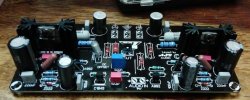
I believe in quality and was not ready to compromise on component quality, which includes audio grade caps (ELNA, Denon, Wima), Precision Resistors (Vishay Dale) and original active devices from ON Semi.
~~Heatsinks
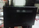
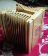
As with any of the Class A amps, this is the most significant component which defines how ‘cool’ is your amp and how “heavy” it is. Usual trend is to have a 250-300mm heatsink for each channel with both transistors mounted on it. I decided to take it a bit further and ordered 4, one for each transistors, each of these weighting 2KGs and the amp already grown to 8Kgs . The below picture is after a failed attempt to anodize it in gold color, the final finish is different.
~~Transformer
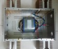
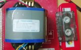
The original design uses a 500VA and I decided to go with the same. I went with R-Core as it is supposed to have the least flux leakage and the cost difference was not that much compared to torroid. The spec is 24V – 0 – 24V and 12V – 0, 512VA, weighs about 7kg.
The cassette is to get a reference for understanding the size.
~~Capacitor bank
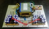
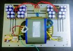
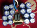
This is the most dreaded part in a JH build as the design is very sensitive to power supply noises. The original design uses about 1F of capacitance to smoothens the DC which uses massive capacitors and eventually adds to the cost. I didn’t want to go with those beer can capacitors mainly due to cost and lack of availability hence opt for 2 separate boards each comprising of 16 4700uf capacitors.
~~Chassis Design
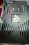
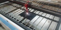
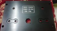
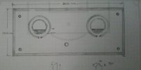
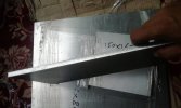
I started with a clean state and my design evolved around the heatsinks, like how to make them look symmetric, what is the best placement for effective heat dissipation etc. Since I am illiterate with CAD and similar software; my only option was the same old pencil and paper. It took me almost 3-4 months to get the complete design after numerus iterations evaluating pros and cons. I decided to build it with 8mm aluminum plates for all sides which will also act as heatsinks.
8mm Plates
I ventured into audio DIY very recently (2018) and was looking for a perfect amp for myself, that was the time I got introduced to Hifivision and stumbled upon this particular thread of Sadik’s. Sadik's JH30.
As most of you know, he is a master craftsman and I always envied his engineering skills. I was a first-time builder neither equipped for such extensive build but didn’t hesitate to grab couple of his pcbs when he listed them for sale in the forum. It was designed by Aniket whos is very well known in DIY space for his DD amps, I didn't have any doubt on the build quality and design of these boards.

The real challenge was that I had no clue where to start but gained confidence after reading about various JH builds around the world and started ordering parts from RS components. All these were happening in 2019 and there were many others discussing about group building JH in various WhatsApp groups. A friend has asked my help in building one for him during one such casual talk which I tried to discourage as I was not confident myself as a builder. But he was very persistent and had more confidence on me, I didn’t have any choice other than to accept the challenge. We had discussed an estimate and delivery deadline of January 2021, with this I started planning activities backwards (I am in to IT and the project management experience really came handy here ).
Below were my to-do lists,
~~ Populate amp boards with high quality components
I believe in quality and was not ready to compromise on component quality, which includes audio grade caps (ELNA, Denon, Wima), Precision Resistors (Vishay Dale) and original active devices from ON Semi.

~~Heatsinks
As with any of the Class A amps, this is the most significant component which defines how ‘cool’ is your amp and how “heavy” it is. Usual trend is to have a 250-300mm heatsink for each channel with both transistors mounted on it. I decided to take it a bit further and ordered 4, one for each transistors, each of these weighting 2KGs and the amp already grown to 8Kgs . The below picture is after a failed attempt to anodize it in gold color, the final finish is different.

~~Transformer
The original design uses a 500VA and I decided to go with the same. I went with R-Core as it is supposed to have the least flux leakage and the cost difference was not that much compared to torroid. The spec is 24V – 0 – 24V and 12V – 0, 512VA, weighs about 7kg.
The cassette is to get a reference for understanding the size.

~~Capacitor bank
This is the most dreaded part in a JH build as the design is very sensitive to power supply noises. The original design uses about 1F of capacitance to smoothens the DC which uses massive capacitors and eventually adds to the cost. I didn’t want to go with those beer can capacitors mainly due to cost and lack of availability hence opt for 2 separate boards each comprising of 16 4700uf capacitors.

~~Chassis Design
I started with a clean state and my design evolved around the heatsinks, like how to make them look symmetric, what is the best placement for effective heat dissipation etc. Since I am illiterate with CAD and similar software; my only option was the same old pencil and paper. It took me almost 3-4 months to get the complete design after numerus iterations evaluating pros and cons. I decided to build it with 8mm aluminum plates for all sides which will also act as heatsinks.

8mm Plates


