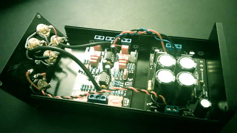
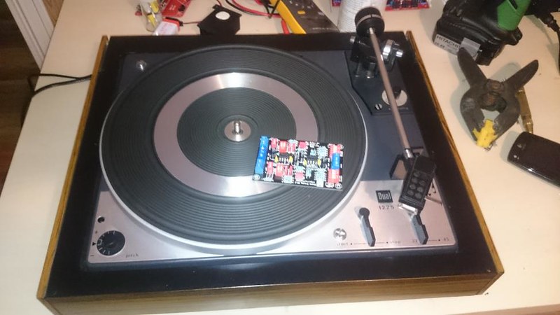
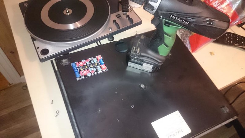
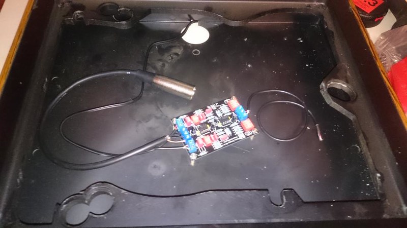
Batery powered DIY CNC phono stage

hi Skrodahl,
while i understand that this may be highly op amp dependent, do you have any numbers on the PSRR/ hum for the specific device you tested?

The PSRR is entirely dependent on the op amp. For OPA2134, the PSRR is typically 106 dB. The typical PSRR for NE5532 is 100 dB.

The measurements show no hum at all. If there was any, they would be a whole lot worse.
 
Those are phenomenal numbers, skrodahl! Thanks for sharing them.
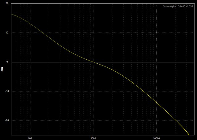
This little fellow does measure really well all-round. Although I can't rule out that I might have been lucky with the tolerance of the components in the circuit I measured on, it's still a very nice phono stage in all regards.
 
I've been made aware that my measurements don't look quite right, and indeed they don't.

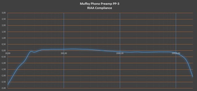
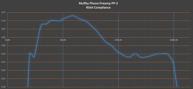
When I measure voltages with the oscilloscope, they differ depending on the horizontal and vertical scale. I have redone the measurements using the QA400 audio analyzer, but they're still not quite right. Especially for the LF portion. I am working on ways of working around the inaccuracies. This will give a better picture though:

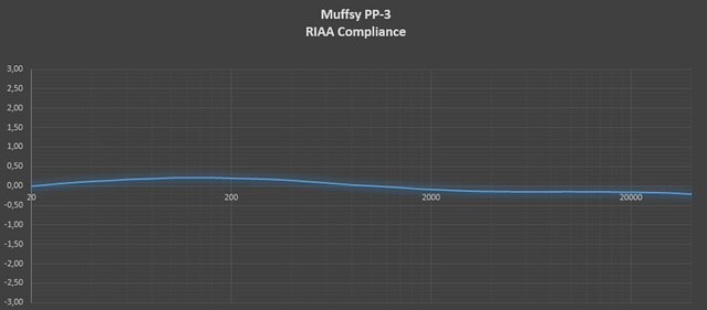
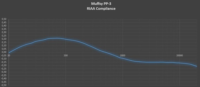
Note that these measurements are done on another phono stage, the components are straight out of the bag with no matching.The Y-axis is in dBr, with the 1 kHz signal at 0 dB.

First just the frequency response, the LF is all squiggly:


Then the RIAA deviance:


Finally, the RIAA deviance with better resolution:
 
This seems to be the best measurements I'm able to provide with my current equipment. What I did was using my Rigol DG1022 as a signal source, and a Uni-T UT61D to measure the RMS output. This gave me a graph that looked much more sane, but the frequency response dropped off at 18-20 kHz and higher.

I can't tell whether it is the Rigol DG1022 signal generator that has a lower output at higher frequencies, or if it is the Uni-T UT61D that can't accurately measure them. I noticed that measuring directly from the DG1022 showed a lower value on the DMM than the signal generator says it's delivering. I then set the SG to deliver the same values as the measured output for all frequencies up to 40 kHz and adjusted for this error.

There's no way I can consistently measure values lower than 0.01 dB, so I stuck with two decimals. This means that the graphs aren't as smooth as they should be.

22484577655_b0db01fe40_z.jpg


The deviance at 20 Hz is -0.01 dB, it's up to +0.21 dB from 100-180 Hz, and down to -0.16 dB at 20 kHz. The deviance goes down to -0.21 dB at 40 kHz, and I haven't measured beyond that.

22458580446_99caa5e714_z.jpg


I have learned a lot since my first (rather strange and squiggly) measurements. Measuring is not at all easy and straight-forward. There are ways to improve them, but the quality of the measuring equipment catches up with you eventually. (I'm still not sure if I got the readings exactly right at above 20 kHz)

The results are very good though, and I hope this little phono stage will keep bringing joy to all its users
 
Re: Battery powered DIY CNC phono stage

You need those resistance to avoid pop n clicks while using switch. It keeps other side reference to ground .

Hi Omishra,

I do not have 100k resistors on the Muffsy PP-3 board.
Do I need to shunt the RCA lives to ground after the Cap?
How dose it effect the 100k input impedance of the upstream Jolida Fusion 3502 integrated?

Regards,
Bela
 
Re: Battery powered DIY CNC phono stage

Dear Omisha,

I do not have 100k shunt resistors on the Muffsy PP-3 board.
Do I just need to shunt the RCA live to ground?
How does this effect the 100k input impedance of the upstream Jolida Fusion 3502 integrated?

Thanks,
Bela
 
Re: Battery powered DIY CNC phono stage

Dear Omisha,

I do not have 100k shunt resistors on the Muffsy PP-3 board.
Do I just need to shunt the RCA live to ground?
How does this effect the 100k input impedance of the upstream Jolida Fusion 3502 integrated?

Thanks,
Bela
That 100K do required. If you are scared then it could be raised to 220K without any issue. Anyway output impedance will be <100R.
 
Re: Battery powered DIY CNC phono stage

Dear Omisha,

I do not have 100k shunt resistors on the Muffsy PP-3 board.
Do I just need to shunt the RCA live to ground?
How does this effect the 100k input impedance of the upstream Jolida Fusion 3502 integrated?

Thanks,
Bela
The resistors will actually lower the output impedance of the phono stage, as they are in parallel with an already very low output impedance. Two resistors in parallel will always have a lower resistance than the smallest resistor.

The reason they are there, is to make sure that the frequency response is intact when connected to an amp/preamp with very low input impedance. (they simply form a high pass filter)

Some of the newer class-D amplifiers can have less than 30k ohm input impedance. In that case, the cutoff frequency will rise from ~1 Hz to ~5 Hz. That's obviously not overly important, but it could be solved with a resistor value that's already in the BOM.

Here are a few more pictures of my latest build:

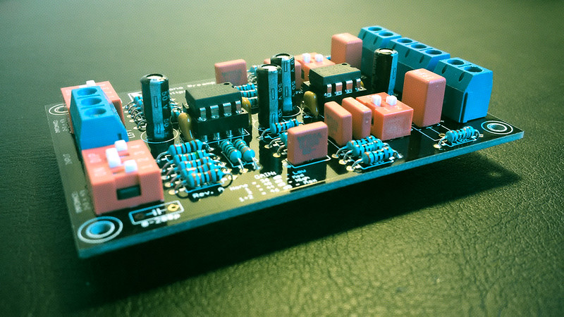
Phono stage, assembled:
22888340069_7279c61db8_c.jpg


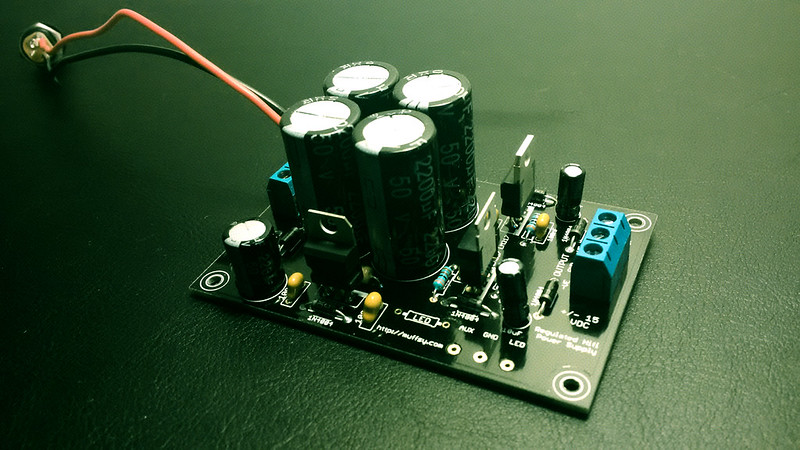
Power supply, assembled:
22627847274_115d650c2a_c.jpg


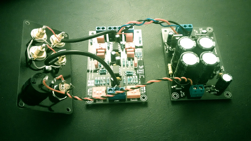
All components connected:
23256204635_fd0bd1e33e_c.jpg


The complete phono stage with back panel, mounted in a B0905 enclosure:
22629088523_d47f41467a_c.jpg
 
Last edited:
I have 0,47uF teflon DC blocking output capacitors since my amp has a 100k input impedance.

If I include the 100k shunt resistors will those effectively half the input impedance of the amp? If so would I need to increase the DC blocking output capacitors to have the same very good bass response?

I have no shunt resistors now and the FT-3 teflon capacitors are connected the the RCA sockets. I can't see/hear any problem just a beautiful, mind-blowing sound.

If those resistors are indeed needed why aren't they on the PCB?

Regards,
Bela

Hi Bela,
The resistors aren't needed in most cases, no worries. They are pull down resistors for the op amp. These resistors are included on the newer revision of the PCB.

Since the output impedance of the op amp is very low, this pull down resistor will actually make the output impedance even lower.
 
Last edited:
Hello friends,

I have been using CNC phono since 2015 with Technics 1200 MKII and Shure M 97Xe/M44-7/M92E. The resistance load set is 47K ohms. It was a great gesture from Om, Sachin and Raghu for this CNC existence on my audio chain. I am pretty happy. I also use NAD PP2 on my second system.

Now I am getting on hold a Shure V15 type III with super track stylus. I may change the stylus to VN35HE from JICO in near future.

I am assuming 47K resistance load would suffice but what about the capacitance load. The recommended cap load is 400 to 500 pf. What I recall from any previous conversation that the cap load set in CNC is 200 to 300 pf. Please correct me if I'm wrong.

Do I need to do any tweak for CNC? Please help as I hold very rudimentary knowledge on electronics.

Thanks in advance,
Sourav
 
Bumped up my question once again. Please revert

You don't need to mod anything. You can always experiment different cap values at 15PF(empty space provided on CNC for cap loading)starting from 33pf to 100 pf. You can buy locally available Ceramic caps. Quality doesn't matter for this purpose. You can solder a two pin PCB connector for easy swapping of caps without soldering/de soldering.

Regards
Sachin
 
Re: Battery powered DIY CNC phono stage

By default, with empty space in CNC and OEM technics wire the capacitance loading is ~125pF. To achieve 400-500pF try sufficient range up to 300pF.
As Sachin suggested, use OPAMP socket pins, or break some legs from ic socket to solder on PCB. Then just pull and swap different capacitors.
 
Last edited:
Thank you Om and Sachin for your valuable feedback. I may take help from FM Bhaskar or another FM Saheb11 here in Kolkata for making this happen. As I am pretty careful touching inside the CNC.

Thanks once again.

Sourav
 
Finally completed my CNC Phono pre and it immediately started singing.

Singing it does, yes sir.

It is absolute bliss.

I suppose the fun starts with the fact that you can admire your handiwork and marvel at the sound it produces at the same time.

DIY is very satisfying, I must say.

The output gain is sufficient and it doesn't have any background noise.

Card is loaded at 47k.

Recently got some mint LPs, enjoying them on this small wonder, pun intended.

It does consume batteries fast, which is ~30 hours, but I was already warned by Sachin.

I'm putting request for PS to him as well.

Will post the findings.

For those who are looking for a Phono pre-amp, look no further.
 
Since sourcing batteries to run the phono kit was becoming a headache

I ordered the Power supply KIT from Sachin.

It arrived and I got to work at once.

Since I'm almost a noob in electronics I kept bugging Sachin a lot and He always guided me through very patiently. So kudos to him once again.

I completed it and carried to a technician for adjusting the voltage, he was mighty impressed with it and exclaimed that it should provide cleanest possible power.

I finally hooked up the tranny and .....

it works...such a flawless power supply.

The background it almost pitch black and I'm yet to properly ground the phono.

I'm a happy and content soul.

Thanks to Sachin for kit and Om for this great design.

Attached are pictures during the work.

[url=https://postimg.org/image/6mhkf366v/] image hosting 5mb[/URL]
 
Get the Wharfedale EVO 4.2 3-Way Standmount Speakers at a Special Offer Price.
Back
Top