Does this qualify as a passive stereo preamp ? :-)

@Amarendra
The Volume control that you built, though it may work for controlling volume, won't have constant impedance across the wiper. I.e. The input impedance will vary continously with the position of your wiper. What you will require is a constant input impedance volume control schematic, where irrespective of the wiper position the input impedance will always be constant.
Sorry but I dont understand. What implication does it have on amp/spkr/output ?
 
Sorry but I dont understand. What implication does it have on amp/spkr/output ?
None on speakers as it will be between turntable and amplifier. On output, the sound will be a bit compressed as the input impedance will be very low at low volume levels. If you have an multimeter at home you can measure the resistance at the input RCA at various volume levels for your confirmation.

If you are using a 10kohm linear vol pot, then theoretically at 9 o'clock position the input resistance will measure 2.5kohm, at 12 o'clock it will measure 5kohm amd so on. If you listen at 8 o'clock it could be as low as 1.5kohm. This could compress the bottom end a bit and you could loose midbass details.

Even the output won't be linear as per the standard LOG taper that is universally accepted for volume control. The best is to go for constant impedance vol control which does not suffer from this problem.
So if I understand you correctly you are suggesting that I relpace the Pot and move to a constant impedance volume pot ?
 
So if I understand you correctly you are suggesting that I relpace the Pot and move to a constant impedance volume pot ?
The current pot can be used only for one channel if you wish to retain them. You may need to get one more set for the other channel.

But I am not sure how the PCB is configured, so won't be able to understand further. If pin nbr 3 of both gangs are shorted then, it won't work for constant impedance vol control.
 
So if I understand you correctly you are suggesting that I relpace the Pot and move to a constant impedance volume pot ?
It is a complicated mechanical system but a neat trick which I will try to explain but it is difficult to explain properly by writing it.
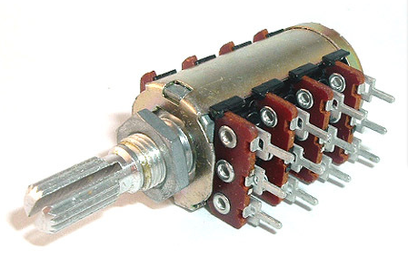
The simple way is to get a quad volume control. The complicated way is to get two dual volume pots.

1. You buy two dual volume pots. or buy a quad unit (2nd diagram below)
2. You connect them using a belt if you buy two dual pots
3. Construct another knob that has got some teeth so that it turns the belt and both the volume control together.
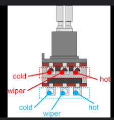
4. On both of the dual pots, connect the middle terminal together. and connect the ends in a criss cross fashion. e.g below you have the cold, hot and wiper terminals. Connect the cold of one terminal to the hot of another terminal. Similarly connect the hot of one terminal to the cold of another terminal. Connect both the wipers together. This becomes the volume control for one channel.


1730114946984.png

1730115616834.png
 
Last edited:
It is a complicated mechanical system but a neat trick which I will try to explain but it is difficult to explain properly by writing it.
The simple way is to get a quad volume control. The complicated way is to get two dual volume pots.

1. You buy two dual volume pots. or buy a quad unit (2nd diagram below)
2. You connect them using a belt if you buy two dual pots
3. Construct another knob that has got some teeth so that it turns the belt and both the volume control together.
4. On both of the dual pots, connect the middle terminal together. and connect the ends in a criss cross fashion. e.g below you have the cold, hot and wiper terminals. Connect the cold of one terminal to the hot of another terminal. Similarly connect the hot of one terminal to the cold of another terminal. Connect both the wipers together. This becomes the volume control for one channel.
Sorry about my basic question but by "cold" you mean ground, by "wiper" you mean output and by "hot" you mean input ?
 
Sorry about my basic question but by "cold" you mean ground, by "wiper" you mean output and by "hot" you mean input ?
No.

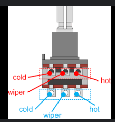
Cold is one of the outer terminal and hot is the other outer terminal. Wiper is always the middle one. If you are holding the volume pot with the spindle facing away from you and the terminals facing upwards, cold one is on the left. Wiper is the middle terminal and hot is on the right. See the photo below of a dual volume pot.
The terminals labeled in red is for the right channel and the terminal labelled in blue is the left (actually it doesn't matter which one you use for right or left).

BTW: I have tried this constant impedance scheme. It makes zero difference to my ears. If it makes a difference to yours, I can't say, but for all practical purpose, it is too much work to get some 0.001 % improvement.


1730183562171.png
 
Passive preamps may overload or cause uneven frequency response, unless some kind of buffer circuit is used. Preamp ususually have a buffer (or a gain circuit) -> vol and or tone controls followed again by a buffer , which is then fed to a power amp. This video explains everything clearly. For project boxes, I use DTH set-top metal boxes, they also have RCA sockets which can be repurposed
 
Passive preamps may overload or cause uneven frequency response, unless some kind of buffer circuit is used. Preamp ususually have a buffer (or a gain circuit) -> vol and or tone controls followed again by a buffer , which is then fed to a power amp. This video explains everything clearly. For project boxes, I use DTH set-top metal boxes, they also have RCA sockets which can be repurposed
Buffers are active device and can also have it's own signature BTW depending upon what transistor, JFET, Opamps or tubes are used as a buffer.
 
Passive preamps may overload or cause uneven frequency response, unless some kind of buffer circuit is used. Preamp ususually have a buffer (or a gain circuit) -> vol and or tone controls followed again by a buffer , which is then fed to a power amp. This video explains everything clearly. For project boxes, I use DTH set-top metal boxes, they also have RCA sockets which can be repurposed
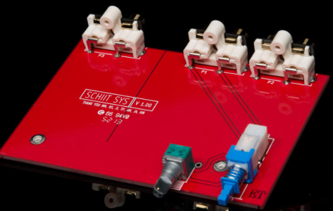
How does Schiit sell its Sys model ? I dont think its anything other than the pot ?

1730193160027.png
 
What can I say? just like many other boutique companies, Schiit Audio does manage to $ell many Schiity things without bothering with proper measurements techniques.
e.g. Back in 2011, I was searching for headphone amp and I came across Schiit Audio Asgard (stop giggling) headphone amplifier. Apart from their tall claims, the company didn't implement proper DC protection during power ON/OFF cycle as they thought relays and protection circuits degrade audio(?).
  • There’s a rather shocking video of an expensive AKG headphone driver being literally deformed by a large DC current when the Asgard is shut off. I’ve never seen anything like it nor had several other people who commented on it.

Jason Stoddard from Schiit Audio responded claiming the power down transient of the Asgard is only 0.10 – 0.15 volts and supposedly similar to a half dozen other headphone amps. Therefore, he argued, the glitch was quite harmless.
But even a 0.1V DC is enough to damage sensitive headphones, while measured DC during power OFF was 1.7 V DC!


I finally went ahead the DIY way and have never bothered myself into buying such boutique audio gears based on any glowing $pon$ored reviews.

How does Schiit sell its Sys model ? I dont think its anything other than the pot ?

coming back to the topic, the first flaw I see in this Sys model is the unnessesary use of a broad PCB, wide/ long track size, thats an open invitation to interferance. A compact layout would have been preferrable. Secondly, the push switch will develop poor contacts due to aging / wear & tear (an inherent design flaw that plagues all push switches alike. Ask any vintage gear owner) when compared to a toggle switch construction, relay implementation would have been even better , but then this is a passive design.
 
Last edited:
Buffers are active device and can also have it's own signature BTW depending upon what transistor, JFET, Opamps or tubes are used as a buffer.
Tubes will color and distort the sound more than any of the other options you mentioned
Majority of audio recordings that we hear today has already passed thru thousands of such buffers/ gain opamps stages in the analog signal path, often thru dreaded JRC 4558 , TL 072/082 opamps or the humble but best NE5532.
So 2 more of such stages won't change results in any significant way -measured or in blind ABX tests. Audiophiles with golden ears and swearing by sighted listening tests will tend to disagree.

correction-
Majority of audio recordings (before DDD) that we hear today have already passed thru hundreds if not thousands of such buffers/ gain opamps stages in the analog signal path, often thru dreaded JRC 4558 , TL 072/082 opamps or the humble but best NE5532.
 
correction-
Majority of audio recordings (before DDD) that we hear today have already passed thru hundreds if not thousands of such buffers/ gain opamps stages in the analog signal path, often thru dreaded JRC 4558 , TL 072/082 opamps or the humble but best NE5532.
This is what purist would want you to believe.
 
This is what purist would want you to believe.
What do those engineers at Philips, TI, National, with state of art testing equipments at their disposal know anything about ultimate hi-fi audio reproduction possible only from some esoteric all-discrete opamps or Tube based audio gears & accessories soaked in snake oil proclaiming "designed by ear" philosophy? Noway a purist can trust datasheets written by some faceless engineer using factory supplied OEM probes and power cables for designing & testing.
 
Last edited:
What can I say? just like many other boutique companies, Schiit Audio does manage to $ell many Schiity things without bothering with proper measurements techniques.
e.g. Back in 2011, I was searching for headphone amp and I came across Schiit Audio Asgard (stop giggling) headphone amplifier. Apart from their tall claims, the company didn't implement proper DC protection during power ON/OFF cycle as they thought relays and protection circuits degrade audio(?).
  • There’s a rather shocking video of an expensive AKG headphone driver being literally deformed by a large DC current when the Asgard is shut off. I’ve never seen anything like it nor had several other people who commented on it.

Jason Stoddard from Schiit Audio responded claiming the power down transient of the Asgard is only 0.10 – 0.15 volts and supposedly similar to a half dozen other headphone amps. Therefore, he argued, the glitch was quite harmless.
But even a 0.1V DC is enough to damage sensitive headphones, while measured DC during power OFF was 1.7 V DC!


I finally went ahead the DIY way and have never bothered myself into buying such boutique audio gears based on any glowing $pon$ored reviews.


coming back to the topic, the first flaw I see in this Sys model is the unnessesary use of a broad PCB, wide/ long track size, thats an open invitation to interferance. A compact layout would have been preferrable. Secondly, the push switch will develop poor contacts due to aging / wear & tear (an inherent design flaw that plagues all push switches alike. Ask any vintage gear owner) when compared to a toggle switch construction, relay implementation would have been even better , but then this is a passive design.
This was first exposed by a guy who goes by the name nwavguy. This guy was hounded by schitt. Such is the power of these companies who fund all these so called audiophile magazines. In fact this guy was challenged by schitt to come with a better headphone amp. And that he did by coming up with the O2 headphone amp (I have that amp and it is fabulous). Read the controversy here
 
Tubes will color and distort the sound more than any of the other options you mentioned
That is so true, but that distortion may be what the user may be desiring and that may be so deep rooted that not even physics or fundamental laws of nature will convince them. The love for particular topology, equipment, cable is addictive like religion. Ever tried to convince a devotee that being human is more important than beliefs? Better let the sleeping dogs remain asleep. Else it just becomes a war that no one can win.
 
This was first exposed by a guy who goes by the name nwavguy. This guy was hounded by schitt. Such is the power of these companies who fund all these so called audiophile magazines. In fact this guy was challenged by schitt to come with a better headphone amp. And that he did by coming up with the O2 headphone amp (I have that amp and it is fabulous). Read the controversy here
IME, even a simple looking harmless wire is a degrade in audio. Let alone active devices.
 
What do those engineers at Philips, TI, National, with state of art testing equipments at their disposal know anything about ultimate hi-fi audio reproduction possible only from some esoteric all-discrete opamps or Tube based audio gears & accessories soaked in snake oil proclaiming "designed by ear" philosophy? Noway a purist can trust datasheets written by some faceless engineer using factory supplied OEM probes and power cables for designing & testing.
But what is your point ? What qualifies as good equipment as per your analysis ? 🙂
 
IME, even a simple looking harmless wire is a degrade in audio. Let alone active devices.
A truly "Unplugged" live band has the best dynamic range, but was available only for the listening pleasures of aristrocats, monarchs, nawabs, maharajas & the fortunate few of that bygone era. Thanks to engineering acomplishments (read-compromises) of the last century, atleast we are lucky enough to enjoy some level of musical bliss in our 1BHK or on the go.

But what is your point ? What qualifies as good equipment as per your analysis ? 🙂
My point is, boutique companies, audiophiles & $pon$ored reviewers alike , often use floral language to describe sound reproduction as dark , veiled, laid back, warm, etc.. If someone claims to see the proverbial "Emperors new clothes", then who am I to disagree?
Qualiities that I look for in any good equipment is proper published specifications / datasheets which can be verified by any 3rd party reviewer (Like Amir from ASR or MIA NwAvGuy). Last but not least, my understanding of that particular equipment design, listening impressions and my budget.
e.g. Similar to Schitt Audio, there is one more company named B*S* who are (in)famous for not publishing full specs of their B*S* products, as such I totally avoid buying products from these companies.
Disclaimer: For my own personal safety and sanity , lets not discuss anything more about that B*S* company 😜

Back to our topic of discussion, I can make buffer circuit for you and then you can compare the same with your passive preamp and decide yourself what is best suited for your purpose
 
Get the Award Winning Diamond 12.3 Floorstanding Speakers on Special Offer
Back
Top