You are using an out of date browser. It may not display this or other websites correctly.
You should upgrade or use an alternative browser.
You should upgrade or use an alternative browser.
Experiments in speaker design for cardioid radiation pattern
- Thread starter Vineethkumar01
- Start date
Vineethkumar01
Well-Known Member
Basic principles remain the same though. The leaking slot behind the driver has similar area as the previous enclosure shape. The tweeter is still not affected due to the properly terminated waveguide formed by the mid driver + its edge rounded housing. The leaking slot port will cause cancellation and cardioid like radiation in the mids and hence reduce the impact from whatever enclosure is behind it.You have changed the design, so measurements need to be taken again
But you are right in the sense that if one wants to know the absolute impact, one has to measure again..
In your new design the driver is naked. This creates a very small distance between the front and rear source. This will give decreased efficiency.
Ideally, the distance should be 1/4wl of the highest frequency of operation of cardioid. Thus you should increase the distance after calculating it and put a 'spacer' on the rear to achieve it
Ideally, the distance should be 1/4wl of the highest frequency of operation of cardioid. Thus you should increase the distance after calculating it and put a 'spacer' on the rear to achieve it
Vineethkumar01
Well-Known Member
Thanks for your suggestions.. 

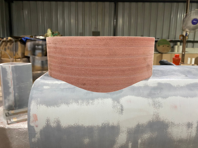
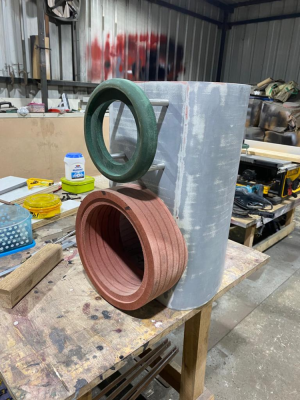
The driver is housed in a 36mm thick circular disc with rounding at the edges where the driver frame meets the disc. This is to act as a proper termination for the waveguide formed by the mid driver for the tweeter. Here is the zoomed in pic of the relevant area of the cabinet
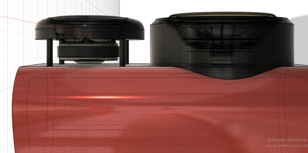
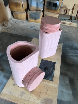
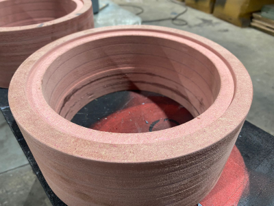
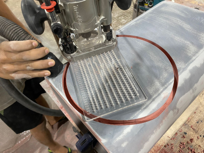
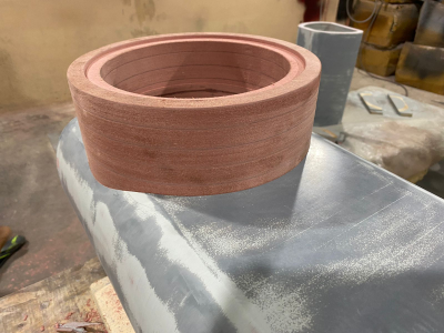
So the distance between the front and rear source just based on the above geometry is let's say atleast 30mm. The gap will anyway be filled with 50mm thick melamine foam rings as in by xps foam prototype.
1) The driver would have started to beam by then and the polar pattern width narrows fast.
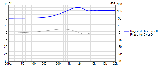
Here is a sim that shows how a flat piston approximation of the driver would behave w.r.t polar pattern width in the above type baffle.
Diffraction sim
Polar pattern (normalized) from above configuration
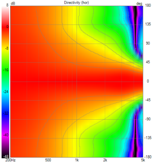
2) The intended crossover with the tweeter (of this coaxial driver) is around 2.5 kHz. Hence from there on, the tweeter will control directivity
Actually, it is not that naked.In your new design the driver is naked.
The driver is housed in a 36mm thick circular disc with rounding at the edges where the driver frame meets the disc. This is to act as a proper termination for the waveguide formed by the mid driver for the tweeter.

So the distance between the front and rear source just based on the above geometry is let's say atleast 30mm. The gap will anyway be filled with 50mm thick melamine foam rings as in by xps foam prototype.
Can you please explain what do you mean by efficiency in this context. Is it the efficiency of the implementation of the cardioid polar pattern?This will give decreased efficiency.
Can you let me know how the 1/4 wl rule is obtained in the context of cardiod implementation. Is that consideration to have roughly co-located sources so that when the dipole meets the monopole, we get cardioid?Ideally, the distance should be 1/4wl of the highest frequency of operation of cardioid.
So as per the 1/4wl rule, I will get cardioid working to approx 2800Hz. which is more than enough sinceThus you should increase the distance after calculating it and put a 'spacer' on the rear to achieve it
1) The driver would have started to beam by then and the polar pattern width narrows fast.
Here is a sim that shows how a flat piston approximation of the driver would behave w.r.t polar pattern width in the above type baffle.
Diffraction sim

Polar pattern (normalized) from above configuration

2) The intended crossover with the tweeter (of this coaxial driver) is around 2.5 kHz. Hence from there on, the tweeter will control directivity
Can you please explain what do you mean by efficiency in this context. Is it the efficiency of the implementation of the cardioid polar pattern?
See, lets say your highest frequency of operation is 2.5khz then 1/4wavelengh is 3.45 cms. This should be the front to rear distance. If distance is higher than this then you will not get good polars, if distance is smaller than this then you will get higher loss due to smaller distance than needed, hence lower efficiency.Can you let me know how the 1/4 wl rule is obtained in the context of cardiod implementation. Is that consideration to have roughly co-located sources so that when the dipole meets the monopole, we get cardioid?
Vineethkumar01
Well-Known Member
Vineethkumar01
Well-Known Member
Vineethkumar01
Well-Known Member
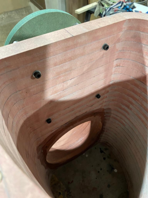
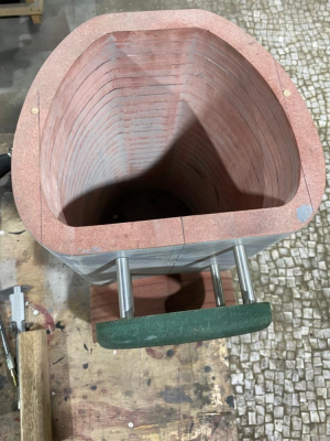
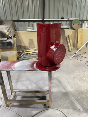
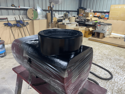
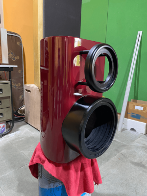
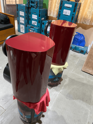
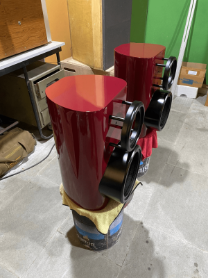
And now they are home and its my turn to complete the build 


To they are ready for measurements

Back of the coaxial driver filled with 55mm thick melamine foam covered with a sock cloth ring (for now). This is for the cardioid midrange


To they are ready for measurements
Back of the coaxial driver filled with 55mm thick melamine foam covered with a sock cloth ring (for now). This is for the cardioid midrange
Vineethkumar01
Well-Known Member
Some starter measurements 
Woofer free air vs in box impedance measurements

Woofer nearfield + impedance in box (not baffle step adjusted)

Sica mid and tweeter impedance (in box)

This much is all I have got today.. The far-field polar measurements will tell us whether the cardiod midrange works (or not)... Fingers crossed for that
Whatever happens, I really love the looks of this speaker..
Woofer free air vs in box impedance measurements
Woofer nearfield + impedance in box (not baffle step adjusted)
Sica mid and tweeter impedance (in box)
This much is all I have got today.. The far-field polar measurements will tell us whether the cardiod midrange works (or not)... Fingers crossed for that
Whatever happens, I really love the looks of this speaker..
Vineethkumar01
Well-Known Member
The speakers are measured (horizontal polars 0 to 180 degrees)

Mid driver (measurements beyond 160 degrees are probably garbage)

tweeter

Woofer

Now a first attempt crossover (reference axis is 10 degrees off axis)


I think it is all working as expected..

Mid driver (measurements beyond 160 degrees are probably garbage)
tweeter
Woofer
Now a first attempt crossover (reference axis is 10 degrees off axis)
I think it is all working as expected..
Vineethkumar01
Well-Known Member
I did the measurements on the coax driver again due to the hint of dipole behaviour in the mids. Turned out that it was a measurement error and the actual speaker behaviour is even better in terms of cardioid midrange behaviour. Here is a linear phase crossover based on new measurements.
A passive crossover version is also in the works


The mysterious right triangle step response

A passive crossover version is also in the works
The mysterious right triangle step response
grindstone
Active Member
Yeah that one is lined-up better. Nice work. I know you're chasing several technical parameters but it's looking like the forward lobe is pretty close to dead-flat so that's nicely done, too.
What I've been wondering about these things Vineeth is where the mid-cone-to-cab-front length dimension shows-up (thinking it should) as a squiggle in the Z or in the FR of the tweeter. __Maybe__ (??) ~3k5 which'd be about a half-wave of 1.93" ? Or maybe you have that whole space loaded with foam or something?
Good to see it seems speakers are multiplying in your home...
Been wondering about you guys (you and @aeroash) and how the big box is going. You guys are always most dangerous when you're not posting Carry on and be well!
What I've been wondering about these things Vineeth is where the mid-cone-to-cab-front length dimension shows-up (thinking it should) as a squiggle in the Z or in the FR of the tweeter. __Maybe__ (??) ~3k5 which'd be about a half-wave of 1.93" ? Or maybe you have that whole space loaded with foam or something?
Good to see it seems speakers are multiplying in your home...
Been wondering about you guys (you and @aeroash) and how the big box is going. You guys are always most dangerous when you're not posting
Last edited:
Vineethkumar01
Well-Known Member
Hi @grindstone
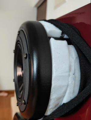
The space behind the back of the coax driver is filled with 55mm thick basotect melamine foam (under the sock cloth) like below
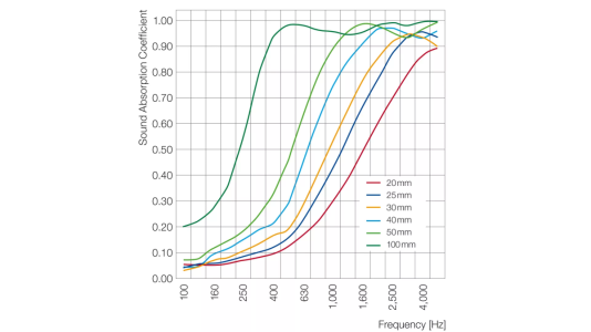
As you might already know, it delays the low frequencies & absorbs the highs, helping create the cardioid radiation pattern in the mids. So the backwave from the mid-cone is also most probably absorbed in the above 1.5k region I think. The sound absorption coefficient of this material is shown below. We can see that 50mm melamine has good absorption above1kHz.
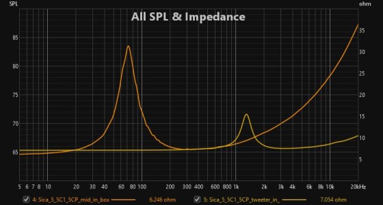
Maybe that is why no impedance wiggles are seen above 1kHz due to the back wave reflection in the midcone's impedance plot shown below?
I am trying to make space for all these speakers at home.. Each one has different flavour to the sound and I like them all
The big boxes are completed and singing well at @aeroash's home. I think he is on travel, currently. Currently the speaker uses a DSP crossover. He has plans to experiment with a passive crossover as well once he gets time..
The space behind the back of the coax driver is filled with 55mm thick basotect melamine foam (under the sock cloth) like below

As you might already know, it delays the low frequencies & absorbs the highs, helping create the cardioid radiation pattern in the mids. So the backwave from the mid-cone is also most probably absorbed in the above 1.5k region I think. The sound absorption coefficient of this material is shown below. We can see that 50mm melamine has good absorption above1kHz.

Maybe that is why no impedance wiggles are seen above 1kHz due to the back wave reflection in the midcone's impedance plot shown below?

I am trying to make space for all these speakers at home.. Each one has different flavour to the sound and I like them all
The big boxes are completed and singing well at @aeroash's home. I think he is on travel, currently. Currently the speaker uses a DSP crossover. He has plans to experiment with a passive crossover as well once he gets time..
Vineethkumar01
Well-Known Member
This speaker is now alive and singing.. 
I tested this crossover first


Here is the reference axis (20 degrees off-axis) measurement I made of the speaker from 50 inches away.
It is almost exactly as per the predicted response in VituixCAD.
The blue line is what I took as the reference based on Vituixcad

So far I like it a lot.. But honeymoon days.. I Need to listen a lot more..
The vocals sounding special is one of the first feelings I got, while listening.
I am missing a bit of bass that I am used to with my big speakers but maybe more tuning needed..
More updates in coming days as I listen more
If anyone is wondering how the speaker looks like (sounds like ) while it is singing, and also want to get some vague idea about the cardioid directivity, see the below video. Offcourse the sound balance will just depend on what you play this video on, but still...
I tested this crossover first
Here is the reference axis (20 degrees off-axis) measurement I made of the speaker from 50 inches away.
It is almost exactly as per the predicted response in VituixCAD.
The blue line is what I took as the reference based on Vituixcad
So far I like it a lot.. But honeymoon days..
The vocals sounding special is one of the first feelings I got, while listening.
I am missing a bit of bass that I am used to with my big speakers but maybe more tuning needed..
More updates in coming days as I listen more
If anyone is wondering how the speaker looks like (sounds like
Last edited:
Vineethkumar01
Well-Known Member
Work on both speakers is complete now.. 
Here they are (for now)

4.2ms gated measurements of the L & R speakers (each taken at 20 degrees off axis)

Measurements of L speaker, R speaker & L+R speakers from listening position (on that chair)

Step response at listening position for L+R speakers

Frequency magnitude & phase response at MLP

ETC at MLP

On the chair, imaging is superb... It feels like sound is coming from behind the monitor in front of me
Time to seriously listen to some music now..
Here they are (for now)
4.2ms gated measurements of the L & R speakers (each taken at 20 degrees off axis)
Measurements of L speaker, R speaker & L+R speakers from listening position (on that chair)
Step response at listening position for L+R speakers
Frequency magnitude & phase response at MLP
ETC at MLP
On the chair, imaging is superb... It feels like sound is coming from behind the monitor in front of me
Time to seriously listen to some music now..
Vineethkumar01
Well-Known Member
Yet another flawed attempt to capture the sound using my mobile phone from the listening position.
But let this be here
Need to get a binaural mic diyed
But let this be here
Need to get a binaural mic diyed
grindstone
Active Member
Thanks for the reply earlier and glad you are listening now  You've covered more DIY'er ground faster than anybody I've ever seen and I can't say enough about your enthusiasm and commitment. Thanks for sharing your projects.
Vineethkumar01
Well-Known Member
A big cardioid 2way + subwoofer concept
The cardioid enclosure for a 15inch driver to house the 15PR400 driver + an EXAR 400 horn
The box is only about 26cm deep from the 'baffle surface'
I like the looks of this
A subwoofer (for crossing over below 80-100 Hz is not shown)


The cardioid enclosure for a 15inch driver to house the 15PR400 driver + an EXAR 400 horn
The box is only about 26cm deep from the 'baffle surface'
I like the looks of this
A subwoofer (for crossing over below 80-100 Hz is not shown)
Passive_audio_enthusiast
Well-Known Member
Job kurianYet another flawed attempt to capture the sound using my mobile phone from the listening position.
But let this be here
Need to get a binaural mic diyed
Wharfedale Linton Heritage Speakers in Walnut finish at a Special Offer Price. BUY now before the price increase.
Similar threads
- Replies
- 28
- Views
- 46K
D


