
.
is anyone seriously intrested?
i ask because you must understand that such a chasis with this level of finish is not cheap(especially considering those huge sinks)
Also if this chasis is built i dont know the technicalities oh how you would place your PCB wrt to the heatsink
is it possible? - i mean placing your PCB;s after the chasis is built with the sinks
do you have to mount the sinks ON the PCB , next to it - i dont know
The heatsinks can be smaller - half the length, and half the height and it will be still be fine. Several of the stock cast aluminium heatsinks from Amar Radio Corp. will work, but they will have to be drilled and tapped precisely.
The chipamp needs to be mounted to the heatsink with a bolt and nut - there needs to be a drilled hole (maybe 3 mm dia.) on the heatsink at the appropriate location. The mounting bolt can be a nylon screw and nut, only slight pressure is required against the heatsink.
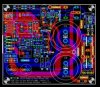
The PCB sits almost flush against the heatsink, and is mounted to the floor of the cabinet using 4 standoffs - again, 4 x 3 mm holes need to be drilled in the floor of the cabinet for each PCB. Dimensions of the PCB are approx. 104mm x 90mm - I am enclosing the layout for reference.
Edit: The alternative is to design an aluminium face-plate for the Dexa chassis, similar to the faceplate on the Modu website, but even simpler - it only needs holes for the switch, 3 LED(s), and 4 mounting holes. Maybe a volume control with knob.
Attachments
Last edited:
")
")

 hyeah:
