My earthing is screwed

I got a 5kv isolation transformer from vertex and the N-E V now is 0V from the output side of the isolation transformer. It is still fluctuating between 10-50V and EB proves to be useless so next course of action is to go the legal way. Huge thanks to all Fm’s who helped and a special mention to @Otpidus @mbhangui @Subbu68 for spending so much time and making me revise my syllabus in EEE hahaha :) Thanks to @Kannan for lending me his isolation transformer to test which gave me the confidence to invest in an isolation transformer.
 
I got a 5kv isolation transformer from vertex and the N-E V now is 0V from the output side of the isolation transformer. It is still fluctuating between 10-50V and EB proves to be useless so next course of action is to go the legal way. Huge thanks to all Fm’s who helped and a special mention to @Otpidus @mbhangui @Subbu68 for spending so much time and making me revise my syllabus in EEE hahaha :) Thanks to @Kannan for lending me his isolation transformer to test which gave me the confidence to invest in an isolation transformer.
As I wrote earlier first step in legal way is through the Regulatory Commission. No need to pay lawyers at this point.
 
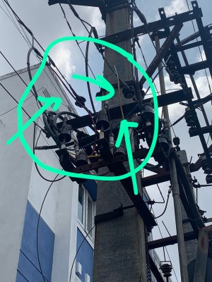
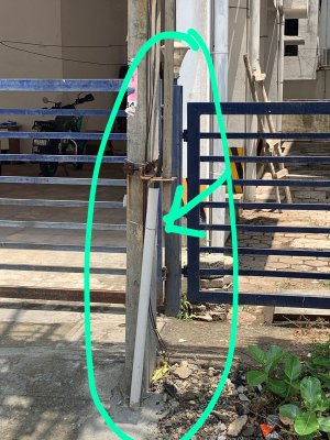
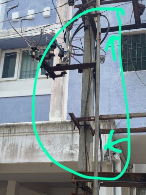
Past three days I observed the N-E V and it’s between 0-3v. Sometimes I noticed it being 0-0.5v which is impossible based on my observations for the past 4 months. Only once or twice it went to 10-14v but just for a brief second and immediately came down to 1v. So I went near the transformer to check if any changes where made. Based on the images EB seemed to have grounded the RYB line. Please find the 3 images. Highlighted arrow marks are the new changes. You can see In the first image Red, Yellow and blue wires connected to the RYB phase in the output side of the transformer. In the second and 3rd image you can see it’s been grounded. Dam it if only they have listened and did this in the first place. I had to spend around 30k to prove its not ground fault. Also I had to sit and revise my electronics basic and still they didn’t respond or acknowledge it’s a fault even after me explaining I am a BE EEE graduate and I understand the basics very well. Just don’t understand how a normal person with no electrical knowledge can deal with these people. I pressured my locality EB through another locality AE contact. Only cause of this pressure they worked but they where not honest. They lied first that they have rectified the fault and without any one knowledge they have come and earthed the RYB. Now if I raise any complaints or go legal they will lie that immediately when I complained that they have rectified the fault by earthing the RYB line.
 

Attachments

  • 5A0EC9DA-E8FC-402A-8CC3-832CB1EB8BE6.jpeg
    5A0EC9DA-E8FC-402A-8CC3-832CB1EB8BE6.jpeg
    271.3 KB · Views: 29
  • 867DB0ED-BFF5-4766-A3BC-3DEDC6EB65A4.jpeg
    867DB0ED-BFF5-4766-A3BC-3DEDC6EB65A4.jpeg
    370.2 KB · Views: 29
  • D19974A1-4096-408E-8618-B254EDFA2886.jpeg
    D19974A1-4096-408E-8618-B254EDFA2886.jpeg
    310.7 KB · Views: 29
Last edited:
Past three days I observed the N-E V and it’s between 0-3v. Sometimes I noticed it being 0-0.5v which is impossible based on my observations for the past 4 months. Only once or twice it went to 10-14v but just for a brief second and immediately came down to 1v. So I went near the transformer to check if any changes where made. Based on the images EB seemed to have grounded the RYB line. Please find the 3 images. Highlighted arrow marks are the new changes. You can see In the first image Red, Yellow and blue wires connected to the RYB phase in the output side of the transformer. In the second and 3rd image you can see it’s been grounded. Dam it if only they have listened and did this in the first place. I had to spend around 30k to prove its not ground fault. Also I had to sit and revise my electronics basic and still they didn’t respond or acknowledge it’s a fault even after me explaining I am a BE EEE graduate and I understand the basics very well. Just don’t understand how a normal person with no electrical knowledge can deal with these people. I pressured my locality EB through another locality AE contact. Only cause of this pressure they worked but they where not honest. They lied first that they have rectified the fault and without any one knowledge they have come and earthed the RYB. Now if I raise any complaints or go legal they will lie that immediately when I complained that they have rectified the fault by earthing the RYB line.
They cannot ground RYB - it will be what we power engineers call a bolted fault. The fuse will blow or if it's a breaker it will trip. If these don't act, the worst case the transformer will blow up.

The star point of the secondary windings of the transformer is grounded to form the neutral for you not the phases R, Y and B.

It is a feeder tapped and taken underground through a cable. What you see in black is a power cable. Inside there will be 4 cores - R, Y, B and Blk that they split and connect to the power lines.

They might have in that course of work corrected the phase that was having the high impedance fault that I suspected.
Totally clueless on what they did and when they did it. Just that there is a change. They have done it secretly without any one’s knowledge. Clear indication they want to cover their ignorance. In the open all I can see is a yellow, blue and red wire connected to each phase respectively and it’s covered with black and grounded. Your explanation clears what must have been done to rectify the fault. Thanks again
 
Totally clueless on what they did and when they did it. Just that there is a change. They have done it secretly without any one’s knowledge. Clear indication they want to cover their ignorance. In the open all I can see is a yellow, blue and red wire connected to each phase respectively and it’s covered with black and grounded. Your explanation clears what must have been done to rectify the fault. Thanks again
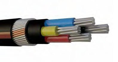
The picture should clear your doubt about what you saw. It's a 6 sq.mm aluminium, PVC insulated, armoured, power cable.

The outer black is the overall sheath, then armour made of steel wires for mechanical protection, inner black sheath or maybe tape, the four aluminium cores R,Y,B for phases and Blk for Neutral.

It may be also without armour if protected by pipes etc.


6-sq-mm-4-core-aluminium-armoured-cable-500x500.jpg
 
The picture should clear your doubt about what you saw. It's a 6 sq.mm aluminium, PVC insulated, armoured, power cable.

The outer black is the overall sheath, then armour made of steel wires for mechanical protection, inner black sheath or maybe tape, the four aluminium cores R,Y,B for phases and Blk for Neutral.

It may be also without armour if protected by pipes etc.


View attachment 69301
Thanks and that explains clearly what they must have done. Hope they have done it properly and there are no other issues. Last night voltage readings L-N was 267. During day time it’s 237-250v.
 
Thanks and that explains clearly what they must have done. Hope they have done it properly and there are no other issues. Last night voltage readings L-N was 267. During day time it’s 237-250v.
Wow!!
267V is at the upper limit. 240V is your nominal voltage.

Since you have a stablilizer it's safe. Still it's good to add a MOV ( over voltage protector) at the input. Not very expensive. Any spike would be bypassed. Even a regular neon lamp would help. It will get damaged but your equipment will be safe.
+1 for Using MOV. Using MOV is a must. If you have the belkin power strips, they have MOV inside. In 2012, all my equipment got saved. The MOVs blew off shorting and blowing the main fuse. I just lost few tubelights which were directly connected to the mains.
 
+1 for Using MOV. Using MOV is a must. If you have the belkin power strips, they have MOV inside. In 2012, all my equipment got saved. The MOVs blew off shorting and blowing the main fuse. I just lost few tubelights which were directly connected to the mains.
You said what I wanted to explain and with real experience.

We have a very stable supply here so never thought of Belkin. I work for the regulator of Abu Dhabi and we take things seriously.
 
Wow!!
267V is at the upper limit. 240V is your nominal voltage.

Since you have a stablilizer it's safe. Still it's good to add a MOV ( over voltage protector) at the input. Not very expensive. Any spike would be bypassed. Even a regular neon lamp would help. It will get damaged but your equipment will be safe.
I don’t have any voltage stabilizer now. Using a MX power strip along with isolation transformer. Yeah 267 is very high and I watched a 2 hours movie in high voltage.
+1 for Using MOV. Using MOV is a must. If you have the belkin power strips, they have MOV inside. In 2012, all my equipment got saved. The MOVs blew off shorting and blowing the main fuse. I just lost few tubelights which were directly connected to the mains.
I have it but not using it now. One dealer suggested I use MX which is better then belkin

MX 6 Universal Socket Surge Protector 16 Amp with Child Safety Shutter and Switch, 2 Port USB Charger (2.1A) with LED Indicator, Spike Suppressor MOV with Power Cord -1.5 mtr https://www.amazon.in/dp/B08SW7276T/ref=cm_sw_r_cp_api_i_9QV46XBRAB7KVSWPFTNM?_encoding=UTF8&psc=1
 
I don’t have any voltage stabilizer now. Using a MX power strip along with isolation transformer. Yeah 267 is very high and I watched a 2 hours movie in high voltage.

I have it but not using it now. One dealer suggested I use MX which is better then belkin

MX 6 Universal Socket Surge Protector 16 Amp with Child Safety Shutter and Switch, 2 Port USB Charger (2.1A) with LED Indicator, Spike Suppressor MOV with Power Cord -1.5 mtr https://www.amazon.in/dp/B08SW7276T/ref=cm_sw_r_cp_api_i_9QV46XBRAB7KVSWPFTNM?_encoding=UTF8&psc=1
I checked the specification of this MX 6 socket. It does not specify the surge protection level expressed as Joules. The higher the better. MX does not indicate if it is a 3 line surge protection.

Belkin 8 way BSV804af2M says it is 900 Joules and 3 line protection.

3 line means it protects surges on L, N or E wires and Belkin specifies the protection level for their models.

Not sure why the dealer said it is better than Belkin.
Yes but as per your suggestion it does come with MOV and fuse. I will get a proper distribution board with power conditioning later on
 
Yes but as per your suggestion it does come with MOV and fuse. I will get a proper distribution board with power conditioning later on
MOV rating decides the level of protection it offers. That device is rated in voltage level and energy it can expend. The more the better.

It is recommended to have around 1000 joule MOV for sensitive equipment. Cheaper the board lower the MOV rating
 
MOV rating decides the level of protection it offers. That device is rated in voltage level and energy it can expend. The more the better.

It is recommended to have around 1000 joule MOV for sensitive equipment. Cheaper the board lower the MOV rating
Fuse will protect only from short circuits. Primarily intended for the power strip...again the fuse rating has to be coordinated with the equipment fuse or the power strip fuse will blow for a short in your amp or other equipment.

Power system protection is an art and very, very complex - maybe some audiophile here will eat me if i said much more complex than designing an amp.
 
MOV rating decides the level of protection it offers. That device is rated in voltage level and energy it can expend. The more the better.

It is recommended to have around 1000 joule MOV for sensitive equipment. Cheaper the board lower the MOV rating
OK but the MX strip is twice the cost of belkin. I hope it is a decent strip.
Power system protection is an art and very, very complex - maybe some audiophile here will eat me if i said much more complex than designing an amp.
True indeed.Learnt so much with the issues i have faced over the past 4 months.
 
Just something I've noted over the years, MX products are cheap Chinese imports (not the good stuff) you can see many of their products on AliExpress.

On another note, I don't really understand chemical earthing or the way it's done here, when I worked in new construction (both domestic and commercial) the electricians would just hammer in earth spikes to the ground (if i recall, they were steel) and clamp the earthing wire, we didn't have separate phases either to residential properties, commercial had 3 phase 440v for many items with seperate control/switch boxes, but then the regular 220~250v was a ring main system which is different to what we use here. A little shock really ****ing hurts due to higher amperage without load.
As far as i know MX is made in india product. Chemical earthing is done using a galvanized electrode and chemical compound.I did it recently. 10 feet hole was dug and a 10 feet rod was put inside the hole filled with chemical compound.
 
As far as i know MX is made in india product. Chemical earthing is done using a galvanized electrode and chemical compound.
I had earlier tried to debug this humbug called chemical earthing over there. It is a commercial trick to cheat gullible and ignorant people.

Earth resistance is the resistance at the interface of the soil and the earth rod. (Refer IEEE 80). Very effective earthing is achieved all over the world including India by simply driving the rod into the ground as @stefan wrote above.

The Indian standards go a step further to specify pipe earthing with coal and salt. Pipe cannot be driven into the ground, so you have to dig a pit and in order to restore the conductivity of the soil that has been disturbed, the charcoal and salt helps. The same applies to plate earthing. If you can compact the soil around the earth rod there's nothing like that. You drive out the air and add water when compacting to get back near the same conductivity. You need space to run the compacting machine. But installers do not do this.

These pipe earthing have a funnel on top to pour water and pipe is perforated to irrigate the soil periodically. Substations in dry areas have an irrigation system that the operators operate or they hose them occasionally to wet the earth pits to keep the resistance down.

This chemical earthing is simply a mixture of bentonite clay and some salts to keep the moisture. It is required only in dry areas where you bore a hole and fill with this mixture to make sure the bonding between the rock and earth rod is contiguous. The rod is then inserted into this "chemical". Even if you are able to drive the earth rod with a pneumatic hammer into the hard & dry soil, due to the vibration and voids in the soil, air that is a supergood insulator will enter the interface of earth rod and surrounding soil to form a high resistance earth pit. Hence, the use of "chemical earthing". In most places in India the proponents of this may be selling it just to steal your money. They know you don't know the science behind it.

If you get a few days of rain once in a while, that will keep the conductivity of soil.

Even in Rayalaseema area (in Telugu it means a land of rocks as I under stand) where I built a 400kV substation we could achieve good low resistance with just soil backfill. Just to reinforce, it was a 400kV station not a 415V transformer. The amount of lightning surges, fault currents, Transient over voltages (TOVs), Switching over voltages, EMIs that can trip the system etc. are infinite compared to an audio system we deal here.

That galvanizing is only to reduce the corrosion not to reduce the earth resistance. Again fooling public.
 
Just something I've noted over the years, MX products are cheap Chinese imports (not the good stuff) you can see many of their products on AliExpress.

On another note, I don't really understand chemical earthing or the way it's done here, when I worked in new construction (both domestic and commercial) the electricians would just hammer in earth spikes to the ground (if i recall, they were steel) and clamp the earthing wire, we didn't have separate phases either to residential properties, commercial had 3 phase 440v for many items with seperate control/switch boxes, but then the regular 220~250v was a ring main system which is different to what we use here. A little shock really ****ing hurts due to higher amperage without load.
True, chemical earthing is a way to fleece ignorant. I explained it earlier.
But salt will dissolve rapidly, especially here with 2-4 metres of rain in the monsoon, as for the coal I don't know if it's charcoal or mined coal? Please elaborate.
Again you are right, salt will dissolve rapidly but the saltiness helps to get back the conductivity. Must be from the heritage of British rule but I think it still continues in India. I have used charcoal not mined coal. It was in the IS and simply followed - young mind then , follow what the boss says.

But now since 25 years I am not in touch with Indian system so not sure if there is any change. From earlier discussion on this thread and another, I believe it is still in vogue.

In most places in India a simple rod should give a good enough low resistance earthing. Maybe a couple more and paralleled. We drive the rods in to the soil in the Middle East. Sometimes up to 10m deep or bored and filled with bentonite and rods installed in them.
 
A beautiful, well-constructed speaker with class-leading soundstage, imaging and bass that is fast, deep, and precise.
Back
Top