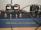
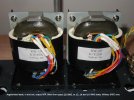
New Design, SE 6005 Directly Coupled Audio Amplifier

Status
Not open for further replies.

drlowmu

Banned
Banned
Joined
Oct 28, 2020
Messages
721
Points
93
Location
Warrensburg, Missouri
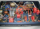
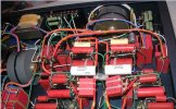
This is a current design and build project, a DIY hobby of mine for many years. It uses a 6005 FINALS tube, which has a 10 Watt (correction - 12 Watt) plate dissipation, and was introduced in the 1950s. Used in car radios and TVs as the FINAL stage, in the USA and in Russia ( an equivalent ) . This tube has a symmetrical construction, an advantage, is a modern design, which I personally prefer to 6BQ5 and Type 45 ST DHT amps I have similarly-built. This amplifier is 70% complete as seen.

I adore two stage directly coupled tube amps, and consider them to be the simplest practical tube amp topology. Such amps require a speaker with 100 dB ( or higher ) sensitivity, and I greatly prefer 15 inch woofers.

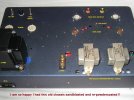
I use professional Movie Theatre speakers, ALTEC VOTT A7-8s, very lightly modified. It is direct radiating into a modest listening room, a front-horn-loaded two-way system. Expected Power output is only 1.5 Watts. This will be the fourth directly coupled stereo amplifier I have DIY designed built for myself - in this same chassis over the last twelve years ! The chassis is sturdy, 14 gauge steel with all welded corners, and a similar thickness bottom plate which acts as a DIY isolation platform.


SNIP.JPG


017 EDITED.jpg


029 EDITED.JPG

Thanks for looking. Best wishes.
 
Last edited by a moderator:
Thanks Jeff for posting your latest build here too. Appreciated.

Wishing you the best with the completion and your listening impressions later.
 
Here below, is an appropriate speaker to use with low-powered tube amps.

I find simple, low powered tube amps can sound the best, in my experiences.

A certain type of speaker, therefore, is a necessity to play the home audio playback hobby most correctly., with the better sounding tube amplifiers.

I feel, you should have ideally a 101 dB or higher sensitivity speaker. I prefer a simple two-way speaker, with a fifteen inch woofer.

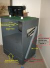
This early ALTEC 825 enclosure has been very lightly DIY modded. It's mods are almost opposite the " common knowledge " audiophile suggestions one finds on line !! I by ear, eliminated much of the stock ALTEC original fiberglass damping, and did very minor bracing, always external. The basic 825 ALTEC enclosure is mostly correct, as originally designed by the ALTEC Engineers.

I much prefer and enjoy listening to a direct / front-radiating 15 inch driver in a partially front-loaded horn ( 135 Hz up ) - such as this. ' Love it.

The DIY damping devices you see, a roll of TUCK brand electrical tape, and a golf ball, is the least expensive and possibly the most effective vibration control device I am aware of. Works gloriously, beneath components, and it is always final-positioned precisely by one's ear. Experiment freely.

The fifteen inch woofer used in this A7-8 is a vintage ALTEC 515B ( alnico ). The compression tweeter is also alnico, a vintage ALTEC 802D. Woofer uses no crossover what so ever, and the large driver operates well, driven full-range.


P1010021 EDITED.jpg


This 825 VOTT enclosure has not been "restored " cosmetically. It is how it came out of a movie theatre.
 
Last edited:
I have had this new amplifier running for two days now. I am pleasantly very surprised, because it is likely the best performing amplifier I have ever heard, as designed and built. In the last dozen years, I have built numerous SE two-stage directly-coupled tube amps using Finals tubes such as : deluxe 300B tubes, 2A3s, Type 45 ST tubes, Type 46 tubes and recently, KT88s.

This little 6006 ( 6AQ5 ) seems to be better performing on sensitive speakers, than all of my prior Finals ( output ) tube choices! This is certainly not a commonly known or accepted result.

I paid careful attention to the B+ power supplies in my designs. My 6005 amp differs in that the B+ to the 6DJ8 Driver tube is passively double-series-shunt-regulated, just as is the B+ to the Beam tetrode's ( 6005's ) separate G2 power supply.

A separate and ultra stable G2 supply is considered the best way to operate a Beam tetrode's G2 grid, but most designers get lazy and short change their implementations. I didn't do that.

The use of those large gray round GTO caps, at the C1 and C2 capacitor positions, feeding the Final's stage, is also highly beneficial to tube amplifier circuits. This cap type, as implemented, resolves the leading edge of musical transients, in a unique ultra-high-performance manner that is simply fantastic to hear on high efficiency speakers, horn loaded and over 100 dB. sensitive.

So far, I am very impressed with how this new amplifier sounds, and it seems to be what I have been searching for, for many decades !! Thanks for viewing and listening to this thread's newest discovery / development.

Drlowmu
 
Hello. I prefer not give out parts-specific schematics of my design work. I will freely discuss it conceptually, and will answer more serious questions one-on-one privately.

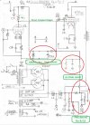
Picture a standard two-stage directly coupled tube amp, except that the B+ to the Input/Driver triode's Plate resistor B+ is double series shunted. ( a shunt is a power resistor to ground, drawing perhaps two times or more current than the audio circuit draws. This greatly lowers the stage's impedance, and it sounds better as a result. )

A double series shunt is two in a row, ( a SHUNT has three components : an R-Dropper, R-Shunt Power resistor to ground, and a film C ) .

I go to the trouble to double shunt the B+ to the triode input section, and also to the G2 element of the 6005 Tetrode. It is very audible. I much prefer double shunting over single shunting a B+ node. Most tube amps we usually see ( 99%, past and present ) are never shunted one time, let alone twice in series.

You can see what I do here :

Double SHUNTED SNIP, Ra and G2 EDITED.jpg

Clear now ??

In the end, we all listen to a music signal-modulated B+ supply.......How good is it ???

The most important thing about this amplifier's thread is, after DIY building DHT ( 2A3 ) amps since 1979, for 42 years, I have finally discovered a Output ( Finals ) tube, that satisfies me. This is a relatively unknown, unaccepted tube, by the audio public. I am so pleased to have learned and experienced this, and to be able to share it publically. Thanks.

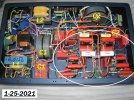
This photo, shows the latest development of my SE direct coupled 6DJ8-6005 stereo amp, as of 1-25.2021.

001 EDITED 1-25 TWO.jpg

I have made several important changes, since the original post, in a way, " designing by ear ".

First, I have changed the L1 and L2 power supply chokes, so as to go lower in DCR ( D.C. Resistances ). Originally I used Stancor C-2708s, which were 10 Ohms DCR each. I did not like the music's presentation with the pair. It was slow and boring. Now, you can view Hammond 159ZAs, as L1 and L2. They are only 6 ohms DCR each, or a total of 12 Ohms DCR between the dual rectifier tubes and the output transformers' primary windings. Now, the presentation is more lively, on time, and I have lost the sense of an amplifier in the system. I have found that chokes need to be as low in DCR as feasible, to get a great sounding, dynamic music presentation, from a tube amplifier.

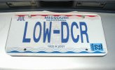
How much do I believe in low DCR in a tube amplifier? Well take a look at my personalized State of Missouri ( USA ) car driver's license plates :

SNIP Low DCR.JPG

Another change made, not shown, was to use vintage GE 5U4GB rectifier tubes , ( ST shaped bottle, octal socket ) in place of the currently available Electro Harmonix 5U4GB ( Russian ) rectifier tubes. " Tube rolling " .

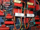
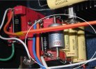
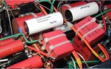
Finally pictured, encircled in white, is further development of the film caps used in the amplifier. I don't use electrolytics in my tube gear, only modern film type caps. Where the average amplifier requires capacitance, in key signal-related positions, I may use four to seven capacitors. High quality film caps, of different microfarad sizes are installed. Each augments the main capacitor, and plays a different part of the music spectrum. This technique, if applied properly, gains additional nuanced musical expression from a tube amplifier, rather than using a single cap in a capacitor position.

The circuit positions circled, encompass the bypassing for two stereo channels, of the amp's (1) 6DJ8 Input tube plate resistor (2) 6DJ8 Cathode resistor, and (3) the 6005's Finals tube cathode resistors.

This entire technique is done by ear, and it is very very expensive, to do properly, so it is seldom seen in the audio arts.

SNIP edited 12.jpg

Thanks for looking. As I further develop this amp, I will possibly post photos of changes.
 
Last edited by a moderator:
DEVELOPMENT as of 1-28-2021 :

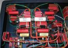
More film cap bypass work has been done. These added film cap values are all chosen by ear, on music playback.

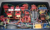
Rear View, 1-28-21 : ( compare to earlier post's photos ) :


SNIP 1.JPG

Front view ( below ), 1-28-21 :

SNIP 20.JPG

FINALS Bypassing encircled below, ( rear view ) on 1-28-21, ( to both SE output transformers ). Starts with a both channel's shared 50 uF WIMA DC LINK cap and a single shared 5 uF large round / grey GTO cap. Six additional film caps were needed, so far.

SNIP 5 REVISED 2.JPG

Closer up ( below ) front view, bypassing detail :

SNIP 28.JPG

Different angle, shows more, 1-28-21 :

SNIP 6 OK.JPG


Next step : this amplifier goes over to a local friend's high efficiency vintage ALTEC system ( VOTT A5's ) - for a comparison to his own 300B amp and his 845 Thoress German monoblock amps.

Japanese Softone RW-20 R-Core SE output transformers ( which play ultra low in distortion, with nice highs ) are due to arrive for this amp, within six weeks.

Thank you - for looking. Best wishes to all.
 
Last edited:
Thanks Jeff for sharing images of your built.

FMs who are keen to listen a different version of this Amplifier are welcomed at my home. Though the final tubes are different, the basic schematic still remain the same. 90% of the parts used are same with the exception of some bypass capacitor and output transformers.
 
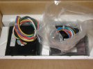
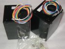
Got possession of two Softone RW-20 Single Ended R-Core output transformers yesterday, and went right to work on them today, to prepare for their use in my new 6005 DC SE amplifier.

Stock leads are pretty decent, and the total DCR of their 5K primary is only 125 Ohms. I design for pulse playback capability, as I seek maximum dynamics through my high efficiency horn system.

So, as standard practice, I try to maximize energy transfer into , inside, and out of the amplifier. This means unusual steps in parts choices ( GTO caps, 6 Ohm inductors ) and in wiring ( lots of m22759/11 , etc. )

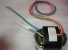
So, here are some pictures of the new R-Core output transformers, and how I prepped them for my use, today. Have fun looking. No, I am not crazy !!! :)


006 NIB.jpg

008.JPG

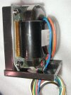
Inner bracket below holds R-Core inside the enclosure. I will run them bare, on the top of my chassis, suspended with brass washers in a pyramid shape, on all four corners.

024.JPG

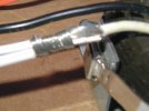
Sorry for the blur below, plenty of contact area , prior to soldering. Whites on left are 12+14 m22759/11, stock white on right is decent, about 18 AWG. Why do this?? " An inch of bad wire can ruin the musical experience".

036 blur.jpg

Secondary below is to speakers, 12+14 Mil Spec to each leg. Low loss. Done.

039 Secondary 12+14 each leg.jpg

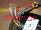
Primary below, see photo for description.

043 EDITED.jpg

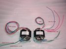
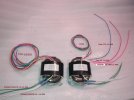
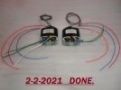
At the end of the day, both trannies are shown below. Only need to do the primary leads on left one, when I am fresh in the morning. This all done neatly was enough for my work session.

055 EDITED.jpg

All this "extra" work is highly audible in my amp building. YMMV.

Thank you very much for looking.
 
Last edited:
Jeff, why are the plate wires thinner than the B+ wires? Any logical reason? Curious to know.
 
Jeff, why are the plate wires thinner than the B+ wires? Any logical reason? Curious to know.
It was hard to read on the second from last photo.

Under dynamic conditions, an output tube, on music's brief instantaneous peaks, will current starve the B+ in the output XFR, and it is audible. By having a larger B+ wire feeding the Output XFR, this AWG wire size offset eliminates that unwanted sonic effect. This ceases to occur during dynamic / pulsed conditions.

Look please at the various schematics I have shown you confidentially, since last year.

A corrected photo edit is below !!! Primary, not secondary.

055 EDITED 2.jpg
 
Last edited:
Both output transformers are now modified, and only after a long upcoming break - in ( 100 to 400 hours ) these will be ready to " rock and roll ".

If a DIYer does not make really careful connections, between added-on leads, these types of modifications can become a degrade rather than an improvement.

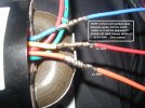
I took a better photo of the second XFR that was finished this morning. You can see where I wrapped the tinned 20 AWG stock leads several times around the 12 or 14 AWG modded ( m22759/11 ) silver plated lead, so as to get plenty of signal contact area, and, I did not leave huge blobs of solder over the joint.

These two outputs are now fully modified, wire - wise, and ready to install, which will be in about a week. Thank you for looking. Hope my posts encourage some people to DIY build their own tube amps !!

In my opinion, two stage, all-tube, direct coupled amplifiers are best - to my ears. I won't bother with anything else. I also prefer professional speakers ( movie theatre, two ways ) rather than consumer speakers, after many many decades of chasing my tail in audio.

001 (2) EDITED.jpg

009 (2) EDITED.jpg
 
Last edited:
That was brilliant piece of soldering drlowmu! Many a time I have done this and never once have I got it like this. Well I will keep trying!
Just out of curiosity what are your tools - solder, iron wattage and bit. Do you use any additional flux?
 
Very interesting & thorough build. CONGRATS!

Have you tested this amp on an o'scope ?

Possible to share some waveforms of the amplfier feeding a load ?
 
That was brilliant piece of soldering drlowmu! Many a time I have done this and never once have I got it like this. Well I will keep trying!
Just out of curiosity what are your tools - solder, iron wattage and bit. Do you use any additional flux?
I use, mostly, a Weller D-550 Soldering gun. It is 325 Watts or 240 Watts, and I use the 325 Watt setting most of the time. Solder is Alpha Reliacore 15 63N/37PB in a large 0.62 inch diameter, to cool the D-550's tip. No additional flux.

It takes a while to learn to use a D-550. Their current model, a D-650, is only 300 Watt maximum, so I buy clean used D-550s, for it's 325 Watt ( extra ) power. You do not leave the trigger depressed for more than several seconds, so that you don't burn-up the tip. The first trigger pull inwards is the highest wattage setting, all the way depressed is the lower setting ( 240 Watts ). I always use the 325 trigger setting. It's not a 240 VAC device, so it would take a large step down XFR to use in your country.

For small-scale soldering, I use an old Weller 60 watt WTCPN with a TC201 Pencil, and various conical tips. I almost always keep the tip clean, residue free, between each use,

Very interesting & thorough build. CONGRATS!

Have you tested this amp on an o'scope ?

Possible to share some waveforms of the amplfier feeding a load ?
Thank you.

I own a TEK 100 MHz dual-trace scope, and various signal generators, but no, I do not test my amps on o'scopes.

I would use a scope only as a last resort, if I could not fix the problem with my Fluke ( 8060A) DMM. I don't recall using my scope once, in the last 15 years.

I have concentrated on two stage, direct coupled tube amps, for 15 years now.

By now, I can precisely ( E.E. theory-wise ) design an all-tube DC SE amp - from scratch. All of my parts selection and builds, however, are DMM tested and mostly - ear tested, as to how it plays complex music. I have reference music tracks I use, to test any amp I build for myself. The extensive use of multiple film bypass caps is done over time, so that the amp ( eventually ) plays all the recorded instruments with full musical expression. The ALTEC VOTT A7-8 speakers are terrific at telling me whats going on, in any build or amplifier circuit change. I can't do this on a scope. The most important final result, in my own humble opinion, is not a scope waveform, but how the amplifier plays the various musical instruments.

I have more upcoming work to do with this build !!

(1) I need to increase my B+, over it's present 433 VDC level. This means a power transformer primary tap change and a re-balancing of the new, higher direct couple voltages.

(2) I need to employ a far more thorough / "all-out" G2 treatment for the output stage, as to it's power supply ( filtering ). This is very important, G2's B+ treatment must be pristine.

(3) and I need to carefully mount, hook-up, and break-in these new Softone RW-20 R-Core low-distortion output transformers.

If its OK, and if there is any interest, I can post updates in this thread, of the future build - progress made.
Feel free please to comment, and interact.

Edit:
Correction : Solder diameter is 0.062 inches, two posts above . Thank you, sorry.

Does corrective editing become impossible, after one hour of age in the post? If so, I will have to triple check what is written.
 
Last edited by a moderator:
Both output transformers are now modified, and only after a long upcoming break - in ( 100 to 400 hours ) these will be ready to " rock and roll ".

If a DIYer does not make really careful connections, between added-on leads, these types of modifications can become a degrade rather than an improvement.

I took a better photo of the second XFR that was finished this morning. You can see where I wrapped the tinned 20 AWG stock leads several times around the 12 or 14 AWG modded ( m22759/11 ) silver plated lead, so as to get plenty of signal contact area, and, I did not leave huge blobs of solder over the joint.

These two outputs are now fully modified, wire - wise, and ready to install, which will be in about a week. Thank you for looking. Hope my posts encourage some people to DIY build their own tube amps !!

In my opinion, two stage, all-tube, direct coupled amplifiers are best - to my ears. I won't bother with anything else. I also prefer professional speakers ( movie theatre, two ways ) rather than consumer speakers, after many many decades of chasing my tail in audio.

View attachment 54387

View attachment 54388
Thanks Jeff for the details. My OPT should arrive by this weekend. I shall use these recommendations in my wirings too.
 
2-13-2021 REPORT

The last week has been very focused on the development of the 6005 SE amplifier.

The ultra-large power transformer, shown in my last post, only lasted a few days on the new chassis, before I decided to remove it.

It was lovely to hear, because of it's 18 Ohms high voltage secondary D.C. Resistance, but the voltage it put out was a shade too high to optimize both tubes' operating points, on the Direct Coupled circuit. I tried, and it was impossible !!

I went back to a Hammond 274BX power transformer, feeding it on it's 115 VAC primary tap. It allowed for a Direct Couple with ideal operating points, for both tubes, my design goal.

What is an tube's ideal operating point, and how does one find it?


The answer is, after you look at graphs and data on a tube, you must then listen to the tube at various plate voltages, and current draws, to really find out what sounds best, on music playback. You won't see this on a o'scope.

As a general guide, one should use higher plate voltages than what is found in 99% of the commercial audio gear, but the plate's currents must be correspondingly reduced, so as to operate the tube's total overall dissipation, in a conservative, and long-tube-life manner. Higher plate voltage operating points allows the tube to swing more volts, resulting in more dynamics and an audible increase in apparent high frequency playback bandwidth. The speaker's playback into your room " opens up ", top to bottom, when so fed.

Allow me to use an example, a popular high gain audio tube, the 12AX7. Most designs will operate it at 150 volts on the plate ( Ea= 150 VDC. ) A few more designs will operate it Ea= 165 VDC.

Historically, 85-90% of all existing audio gear will operate the 12AX7 tube at 150 VDC to 165 VDC on the plate, or lower.

Maybe 5 to 10% of the tube audio circuits will offer it running at 185 VDC on the plate ( Ea=185 VDC . ) Note : this Ea 185 VDC equipment sounds vastly superior to 150-165 VDC. The tube is starting to swing and DO something !!!

The best example of this can be traced to a gentleman I personally knew, who started a company called Audio Research, William Zane Johnson. He knew enough to operate the 12AX7 at high voltages with reduced currents. That is precisely why people were " floored " in the 1970s, when he introduced his famous SP3-A1 tube preamp, to rave reviews and consumer demand. Look at the schematic. He starts the preamp with a 500 VDC B+ supply, which he actively regulates down to 440 VDC, and feeds the 12AX7s with 440 VDC of B+ ( not on the plate ! ) . This allows the use of high value plate resistors, and cathode resistors, and the tube SWINGS VOLTAGEs, and actually does something, musically, VS all the preceding preamplifiers known to the public !! Yes, Bill was smart - knew how to operate the tube, no one before him did so to my knowledge.

A superb operating point for the 12AX7, where it sounds the best, is Ea= 195 VDC, with only 3/4s of a milliampere of current. Listen to that, you will like it musically !!

Back to my 6005 amp. I had never used a 6DJ8 before, and I had to find it's best Operating Point, VDC-wise. Well, I started at about 165 VDC, and recorded all the key voltages, after listening to reference music selections. In the last week, I must have made 15 changes ( higher in plate voltage), listening intently to the same music selections, and documenting each change with full amplifier voltage and current measurements.

At last , yesterday, on 2-12-2021, I arrived where I wanted to be, VDC wise and total tube dissipation wise ( low and conservative and long lasting ). Depending upon one's line voltage in the USA where I reside, I ended up selecting by ear 204 VDC ( 120 VAC line ) and 210.8 VDC ( 125 VAC line ), as the best performing VDC plate voltages for a 6DJ8.

The differences are so easy to hear, and vast, on my ALTEC A7-8 Voice of the Theatre speakers. I am very pleased, to have now done this listening work, as it will apply to any 6DJ8, or its variants ( 6922, or what I really expect to use, a Russian 6N23P-EV triode. )

Additionally, with these 15 circuit changes, I was also able to optimize the operation of the 6005 FINALS tubes. I operate output tubes conservatively, usually at 62% of the tube's maximum rated dissipation. 62% is the Golden Ratio percentage, and one of my goals, for best long-term tube sound and long life.

I ended up with my 6005s measured operating at 61.11% ( of maximum rated dissipation ) at 120 VAC and 66.84% at 125 VAC, which is a reasonable compromise on total tube dissipation, and close to the Golden Ratio.

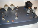
So I have no sexy pictures to show you of the last week's work. But as of today, I am very satisfied with the week's listening and measuring results. My gut feeling right now is, this will become the best sounding amp I have ever built, given some normal development time. No one in audio has ever executed a 6005 amp as this is being done, that is for sure.

Still haven't mounted the Softone output transformers, nor installed 6N23P-EVs. This past week's work took priority.

Here is some compelling information on R-Core transformers, which relates directly to the unique Softone RW-20.

https://www.custommag.com/r-core-transformers.

Also, correction, in my first post, an error. The plate dissipation of a 6005 is 12 Watts, not 10 Watts.
 
Last edited:
@drlowmu

Thanks Jeff for the detailed mod report on the 6005. You have documented them quite well for DIYers to know what to do and what to expect. Imo, if you are going DIY it's always good to leave some room for experimentation to suit personal choices and preferences, otherwise the very purpose of going DIY is not achieved. Most DIYers I have seen typically built from a known published design and are then stuck with it. It's very important when you are new to DIY, you need a guru/ mentor like you, who not only shares the design, but take you through the complete built process explaining how to arrive at the various operating voltages, how to do the math, which components to consider, where to buy and with pros and cons of each components. DIYers should take the benefit of your vast experience in tube amplifier designing and building and learn if they are really passionate about what they are doing. I have not come across any person in my entire life who is so passionate about what he is doing, and what standards of quality and satisfaction one sets for oneself and others for whom you are a mentor. I consider myself as fortunate to have found you as my mentor/ guide/ guru in my DIY tube amp built project. A big thank you to you for accepting me as your student/ apprentice.
 
Holy smokes. I am blushing !!

I have always had mentors myself. First, the late Robert W. Fulton, ( Fulton Musical Industries ) and now, for the last 30 years, the fabulous Dennis Fraker ( Serious Stereo ). Both became close personal friends.

Have fun.


and this, starting right at the red monoblock amps photo :

 
2-17-2021 REPORT

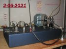
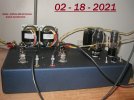
Installed and wired-in the new R-Core output transformers. These are wonderful !!

003 edited.jpg

012 edited.jpg

013 edited.jpg

Military Spec wire is m22759/11. Multi stranded copper, silver plated, teflon jacket.

A second time, for your information : R-Core output transformers are different, and uniquely superior to all other types, as follows :

https://www.custommag.com/r-core-transformers

I have decided to name this new design " the REVELATION ", and am looking into a brass name tag design.

Thank you, for looking .
 
Last edited:
Status
Not open for further replies.
Purchase the Audiolab 6000A Integrated Amplifier at a special offer price.
Back
Top