Subwoofer AMP board is burnt. How to find suitable replacement?

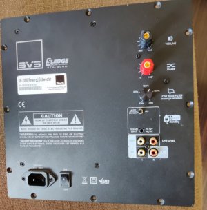
I am in the same boat. One of my SVS SB2000 sub is not turning on. I opened it up yesterday, appears plate amp. is damaged. I disconnected the plate amp. I have some questions on trying to connect to an external amp:
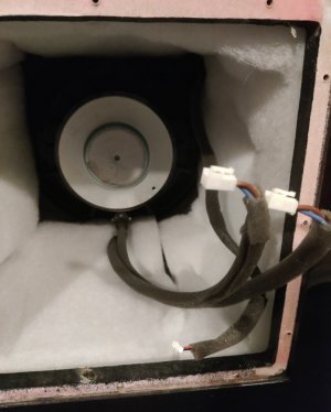
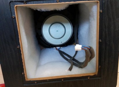
1. There are 4 wires (2 blue and 2 brown) connected to the driver.
2. On the amp side - each blue and brown are terminated into a quick connect, so 2 quick connects, and connected to the amp board.
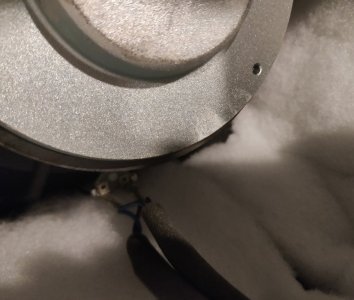
3. On the driver side only similar coloured wires, that is brown and blue are connected to the terminals.
My question, when I connect to an external amp, I have to form similar coloured wires into a pair right and connect to the amp. speaker +ve and -ve outputs? I wonder why they are mixed to the plate amp connector?
Also should I be worried that there is no EQ etc. being applied by this direct connection? I will be using my receiver cross over so only 80hz and below signals will travel to the sub amplifier.
Thanks,
Cheers,
Sid
Some photo of the blue and brown wire as they are leading from the drive terminal would help. Also photo of the plate amp would help. Are there any fuses on the plate amp board?

EDIT: I found this from google search. The brown goes to positive terminal on the speaker (red dot on the terminal). There are two wires for each to increase the current carrying capacity.
img-20190401-171042_934661.jpg
 
Last edited:
Some photo of the blue and brown wire as they are leading from the drive terminal would help. Also photo of the plate amp would help. Are there any fuses on the plate amp board?

EDIT: I found this from google search. The brown goes to positive terminal on the speaker (red dot on the terminal). There are two wires for each to increase the current carrying capacity.
View attachment 75182
Yes this is how the arrangement is in my sub as well, thanks so much for the photo. So when I cut the quick connectors at the amp. end do I join the browns and blues and connect browns to the +ve and blues to the -ve speaker terminals of my external power amp.?
The other quick connect is for the led so it is not important.
Regardless I will take photos of my plate amp. and post.
Cheers,
Sid
1. Connect brown + brown together
2. Connect blue + blue together

connect the two brown wires both to the +ve output of the amp. This will be usually red
connect the two blue wires both to the -ve output of the amp. This will be usually black.
 
If you have speaker level inputs on the back plate, you can connect both the brown wires to the red speaker level input and both the blue wires to the black speaker level input. Then you just need to connect the subwoofer using any speaker wire with banana/spade connectors from your external amp to the the subwoofer speaker input.

Just show me the inside view of the back plate that you have removed. Hope the entire board can be removed without removing the speaker inputs.

If you connect that way, it will be neat.
 
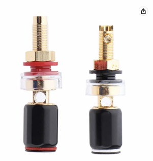
Unfortunately there are no speaker inputs. So my plan is either remove the phase and crossover knobs and put some speaker binding posts there or drill a couple of small holes.
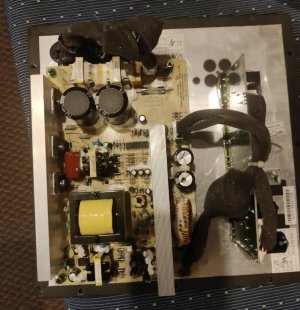
Attached is pic of the plate amp connected to the sub. I will remove it and post pics tomorrow of the inside as well.
Ok. This looks promising. You can remove entire electronics. You will be left with open holes on that plate. There are four holes for the RCA line level. We can utilize two of these holes for putting speaker binding posts which have a insulated plastic sleeve. The the plastic sleeve just need to fit into the hole. Rather than making two new holes, it is easier to widen the existing holes using a drill bit which has the same diameter as the plastic sleeve. If you look at the below picture you will understand
1676382085604.png
 
These are the pics of my sub and the plate amp disconnected.
Cheers,
Sid
View attachment 75187
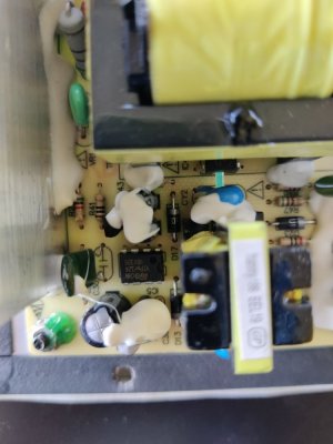
On the top right of the left horizontal board, there is a glass cartridge fuse. Do you have a multimeter to see if the fuse is not blown? Alternatively, can you take a closeup picture of the fuse?

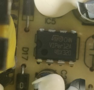
This is a SMPS board. Most likely the fuse has blown or the SMPS ic has blown. The SMPS ic is at the bottom left (8 pin ic). If you could take a close picture or post what is written on the IC, it would help. The board can be brought back to life if the ic is blown and if it is replaced.

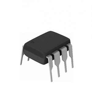
The ic looks like this
1676430753468.png
 
Last edited:
If the led is not coming on (even in always on position) it is most likely the SMPS ic. It could be the fuse too in which case just 4-5 rupees will bring back your board to life. These SMPS ic are blowing all over the country because the country's voltage standards have been made same as Afghanistan to benefit one or two private players. This country can have voltage as high as 264 volts which gives 373 volts DC. The max dc voltage these ICs can tolerate is 375 volts dc.
 
On the top right of the left horizontal board, there is a glass cartridge fuse. Do you have a multimeter to see if the fuse is not blown? Alternatively, can you take a closeup picture of the fuse?

This is a SMPS board. Most likely the fuse has blown or the SMPS ic has blown. The SMPS ic is at the bottom left (8 pin ic). If you could take a close picture or post what is written on the IC, it would help. The board can be brought back to life if the ic is blown and if it is replaced.

The ic looks like this
View attachment 75190
The fuse is working, I checked with a continuity meter.
I think this is the IC.
Cheers,
Sidic.jpg
 
This is a SMPS ic available for Rs 55. Order it and ask any mobile repair shop to replace that. Buy 2-3 ics. These are made in China and few in a batch do not work. Ever since the covid when the power companies increased the voltages on the sly I have lost quite a few power supplies because of these ICs - my yamaha avr standby SMPS, RO water purifier SMPS, my PC SMPS, iphone charger to name a few. Whenever I order these IC, one of them turns out to be bad. So I always order 4 of them. No harm in trying. Worst case you will loose around 100 bucks if the fault is somewhere else.


This is a Low power offline switched-mode power supply primary switcher, datasheet here
 
Sorry I made a mistake in the link. The link I posted is a smd version. You need the non-smd version. Let me search and locate

Here is the link


Last edited:
And also check the two electrolytic capacitors (one below the SMPS ic and one above) do not exhibit any bulge. In a SMPS, these capacitors are highly stressed and failure of the caps also leads to SMPS ic failure. These can be replaced with Keltron caps if they show signs of bulging.
 
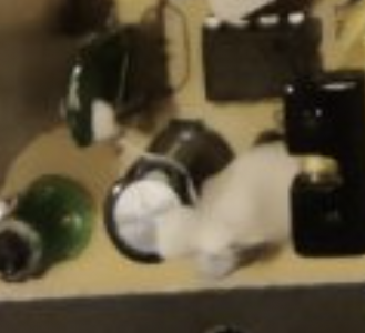
@sidvee Does this capacitor look as if the top metal surface is bulging out (convex shape)? All other capacitors have concave top metal surface. Since I don't have a close up picture of this capacitor I can't make that out clearly from the picture you posted
1676439370991.png
 
@sidvee Does this capacitor look as if the top metal surface is bulging out (convex shape)? All other capacitors have concave top metal surface. Since I don't have a close up picture of this capacitor I can't make that out clearly from the picture you posted
View attachment 75192
I will revert back in the evening.
Cheers,
Sid
 
Anyways I managed to get a couple of binding posts in. Will connect an external amp. over the weekend and check out how it performs.
Thanks all for the help, I would not have known what to do without all of your help.
Cheers,
Sid
amp3.jpg
 
Yes that capacitor looks like it is damaged with a bulge.
Cheers,
Sid
View attachment 75200
Yup. The capacitor has gone bad. Typically this is what mostly happens in SMPS failures. The stressed out electrolytic capacitor become bad leading to SMPS failure. Most likely the VIPer 12a chip is fine because these chips have built-in safety turn off. You will have to remove the glue carefully and remove the capacitor and put a capactor of the same microfarad value and with the same voltage or higher rating. The board will start operating once you replace the capacitor or the capacitor and the chip.

Replacing the capacitor is a very easy job. I'm sure there will be some FM in Hyderabad who can do this for you. Just a 2 min job. Removing the IC however requires a de-soldering hot air gun. Can be done with a soldering rod and desoldering braid too. But one has to be careful in not overheating and damaging the copper track on the PCB.

There is one more capacitor (smaller value) just above the IC in the photo above. The top is covered with glue. Remove the glue and confirm if that capacitor top surface is not bulging.

Was this subwoofer powered without a voltage stabilzer?
 
Last edited:
For excellent sound that won't break the bank, the 5 Star Award Winning Wharfedale Diamond 12.1 Bookshelf Speakers is the one to consider!
Back
Top