Time for another DIY Speaker project

Thanks a lot for chipping in @navin advani much appreciated.
CLD works best if the stiffness and density of the 2 layers are as different as possible. I have not used Aluminium but I have used closed cell foam, resin bonded fibreglass (FRP) and lead sheet as the CLD layer.
From whatever little my understanding of the Acoustics, I too hold the same opinion. Incidentally, using thin sheet of lead is what I too was considering and even discussed about it with @Vineethkumar01 just yesterday.
For any others interested like me, I am posting this link which shows more pics and gives more details about this build: https://www.audiocircle.com/index.php?topic=110639.0
Thanks so much for sharing this. Much appreciated.
Looking very good!
Thanks so much. The crossover is almost complete. Got delayed as Mr. Mukherjee of Syco India was indisposed.
66% of the cost of building the box? o_O
Yes. The cabinets cost me 9k and the three pairs of Zantzen Binding Posts cost me all of 6k.
 
From whatever little my understanding of the Acoustics, I too hold the same opinion. Incidentally, using thin sheet of lead is what I too was considering and even discussed about it with @Vineethkumar01 just yesterday.
Doing that would not amount to anything even close to CLD. It is mass loading the walls and it has it's benefits. CLD is a different animal altogether. Implementing CLD properly at this stage in your already built box would be difficult. Your box is braced appropriately and I suggest you leave it that way. If the worm still turns, look at Tuf-Kote sound deadening coating or MMT Acoustics mass loaded vinyl sheets, both available on Amazon.
 
Doing that would not amount to anything even close to CLD. It is mass loading the walls and it has it's benefits. CLD is a different animal altogether. Implementing CLD properly at this stage in your already built box would be difficult.
Sorry for not explaining fully. Yeah, lead layer by itself will only lead to mass loading. I'd use a shearing layer in between the MDF box and the lead layer of 1-2 mm. Over it, may be 3 mm teak ply.
Your box is braced appropriately and I suggest you leave it that way. If the worm still turns, look at Tuf-Kote sound deadening coating or MMT Acoustics mass loaded vinyl sheets, both available on Amazon.
Thanks so much for the pointers. My plan would be to listen to them first and embark upon the CLD journey only if it's warranted.
 
Sorry for not explaining fully. Yeah, lead layer by itself will only lead to mass loading. I'd use a shearing layer in between the MDF box and the lead layer of 1-2 mm. Over it, may be 3 mm teak ply.

Thanks so much for the pointers. My plan would be to listen to them first and embark upon the CLD journey
only if it's warranted.
The way your box is currently with the bracing et al, I'd be willing to bet that implementing anything further would only show up in COMSOL and not audibly. :p
If it were me, I'd just spend around 500 bucks to paint the insides with the Tuf-Kote and call it done!
 
If it were me, I'd just spend around 500 bucks to paint the insides with the Tuf-Kote and call it done!
Hmm. Let's see. I'll cross the bridge when it comes. :)

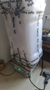
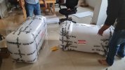
An update. The cross-overs have been made and ready for installation at Calcutta. The speakers have been packed well and ready for transportation by courier. After packing, they're weighing a hefty 19.9 kgs each :eek: :eek:
IMG-20220208-WA0037.jpg
IMG-20220208-WA0038.jpg
Installation of x-over, wiring up and tuning by the ear will be done at Calcutta by my friend Romit, who made the DIY speakers that I'm currently using.
 
An update:

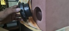
The speakers have reached my friend Romit at Calcutta and the tuning process has started. He has encountered a problem. The speakers were sounding boomy which he had squarely attributed to the port diameter and length.

To be honest, the box maker did ask me to send him the ports of right dimensions as his would not match but since I was too busy shifting to Mumbai, I had asked him to make his own arrangements. He found something in his bin and had sent me the pics and dimensions but I, owning to my predicament, couldn't verify the dimensions with the original design; big mistake.

As per the design, the port should have 2" dia and 3" long with flares at both ends. The end to end length with flares should be 8".

But the diameter of the port that has been fitted is said to be 3" and the flare is 4". However, the length is not much. Actually, it can be described as a " port-head" if i may term it that.

I've suggested that we attach a commonly available PVC plumbing pipe to extend the length.
IMG-20220215-WA0008.jpg
IMG-20220215-WA0011.jpg
Now, the point is, should I maintain the pipe dia @ 3" and calculate the length with the software that @keith_correa had linked earlier in the thread or would it help if I taper the pipe gradually so that it would be 2" at the end, which can then be fitted with matching flare?

Looking forward to your views.
 
An update:

The speakers have reached my friend Romit at Calcutta and the tuning process has started. He has encountered a problem. The speakers were sounding boomy which he had squarely attributed to the port diameter and length.

To be honest, the box maker did ask me to send him the ports of right dimensions as his would not match but since I was too busy shifting to Mumbai, I had asked him to make his own arrangements. He found something in his bin and had sent me the pics and dimensions but I, owning to my predicament, couldn't verify the dimensions with the original design; big mistake.

As per the design, the port should have 2" dia and 3" long with flares at both ends. The end to end length with flares should be 8".

But the diameter of the port that has been fitted is said to be 3" and the flare is 4". However, the length is not much. Actually, it can be described as a " port-head" if i may term it that.

I've suggested that we attach a commonly available PVC plumbing pipe to extend the length.
View attachment 67342
View attachment 67343
Now, the point is, should I maintain the pipe dia @ 3" and calculate the length with the software that @keith_correa had linked earlier in the thread or would it help if I taper the pipe gradually so that it would be 2" at the end, which can then be fitted with matching flare?

Looking forward to your views.
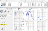
I dont know much about the software Keith has mentioned. Just did some rough calculations in VituixCAD. With a 2 dia inch and 8 inch long port, it does show a tuning frequency f3 of around 34Hz. Here is the data.

STATISTICS
f3 34.6 Hz
f6 29.5 Hz
f10 25.6 Hz
Zmin 3.1 Ohm @ 302 Hz
Zmax 12.2 Ohm @ 59.1 Hz
GDmax 20.1 ms @ 27.9 Hz
XmaxC 5.9 mm @ 5 Hz
VmaxR 8.3 m/s @ 28.7 Hz
Pmax 2.5 VA @ 302 Hz
-------------------------------------------------------------
DRIVER: Dayton Audio RS180-4, 1 pcs in series
n0 0.20 % Reference efficiency
SPL 85.1 dB/W Sensitivity
USPL 89.2 dB/2.83 Sensitivity
EBP 65.1 Efficiency bandwidth product
Dd 12.6 cm Effective diameter of driver
Vd 75.0 cm^3 Maximum linear volume of displacement
Cas 1.51E-7 m^5/N Acoustic equivalent of Cms
Mas 1.14E2 kg/m^4 Acoustic equivalent of Mms+Mme
Ras 1.29E4 Ns/m^5 Acoustic equivalent of Rms
Rae 4.58E4 Ns/m^5 Acoustic equivalent of Re+Rg
-------------------------------------------------------------
BOX REAR 1: Vb=24.0 l, Ql=15.0
Fb 34.0 Hz System resonance frequency
Cab 1.7E-7 m^5/N Acoustic compliance of air in enclosure
Rab 5.52E2 Ns/m^5 Acoustic resistance due to absorption
Ral 4.14E5 Ns/m^5 Acoustic resistance due to leakage
-------------------------------------------------------------
VENT REAR 1: Dv=5.0 cm, Lv=17.0 cm
Sp 19.6 cm^2 Effective area of port
Map 1.29E2 kg/m^4 Acoustic mass of air in port
Rap 4.6E2 Ns/m^5 Acoustic resistance of port losses


If you want ro get the same tuning using a 3inch dia port, it looks like you need a length of the port around 40+ cm which looks difficult to fit in that box. Relevant plots attached. Haven't modeled port flares though.
 

Attachments

  • vented_box.png
    vented_box.png
    430.1 KB · Views: 18
Curt & Jim used a Precision Port on their box. The flares on Precision Ports are very different from the run of the mill flared ends available off the shelf, so it would be wrong to substitute PP flares for the ones you're using and use the length they used originally. The original design tuned the box to 34 Hz. Go to: http://www.psp-inc.com/tools2.html and enter volume as 0.84, tuning frequency as 34, port diameter as 2, # of ports as 1 and hit "calculate". It will throw up 8.255 as the Precision Port flare length port required. This is applicable ONLY for a Precision Port!

You have 10" internal depth available inside the box.

For a 34 Hz box tuning in a 24 liter box, with a 2" ID port - the port length is 7.18 inches
For a 34 Hz box tuning in a 24 liter box, with a 3" ID port - the port length is 17.15 inches

would it help if I taper the pipe gradually so that it would be 2" at the end, which can then be fitted with matching flare?
No!!!!
 
Hmm. Let's see. I'll cross the bridge when it comes. :)

An update. The cross-overs have been made and ready for installation at Calcutta. The speakers have been packed well and ready for transportation by courier. After packing, they're weighing a hefty 19.9 kgs each :eek: :eek:
View attachment 67042
View attachment 67043
Installation of x-over, wiring up and tuning by the ear will be done at Calcutta by my friend Romit, who made the DIY speakers that I'm currently using.
Did eight audio built Cabinet ?
 
@captrajesh, @keith_correa, @Vineethkumar01

I have a pair of Zaph Audio speakers built by @manniraj
The 18/20 mm MDF that is normally recommended is for board density or ease of working?
Does it make sense to re-host these into a new cabinet made out of Fundermax sheet?
This material is used for external wall cladding. The material is very hard, dense and rigid.
I have some leftover 12mm sheet to try with.

Cheers,
Raghu
Hi Raghu,

This is the first time I am hearing about this material called Fundermax. So i dont know much about it. :)

But in general, I think if you already have a reasonably inert cabinet, you might not get much audible improvements by housing the drivers in a new cabinet with the same technical specifications. If the current cabinet is "bad" though, it is an entirely different matter. I am attaching a PDF by Scott Hinson that talks about sheet good materials for speaker cabinet construction. It compares between the advantages and disadvantages of different materials. Out of all that is there in the pdf, this line is the most important "There is no magic material, and our construction methods/design will contribute more substantially to our success in building an inert high quality speaker cabinet than the sheet good material"

At the end of the day, as said above, the acoustic design is what matters much more than the cabinet material as long as the cabinet is built reasonably good. Your speaker being a 'zaph audio' design, I think the acoustic design part might have been taken care of to the best extent possible by John Krutke :)

Thanks
Vineeth
 

Attachments

I'm getting some carpentry work done for the home. Whenever this happens, some crazy ideas pop up related to audio.
One such idea is the speaker re-housing (not committed). The other is an amp re-housing in a wooden cabinet (committed).
Let's see how things pan out.

Cheers,
Raghu
 
@raghupb even I have never heard this material, but it does sounds like out of Mars or some other galaxy it fell on earth ;)

Jokes apart the cabinet I built in fact my first ever foray into the carpentry used MDF with double layer for stiffening. Hence they are so heavy and on top of that 4mm veneer sheet with the polish. So I guess its already very dense so nothing much you will get the benefit by putting them into other cabinets in my opinion.
 
I dont know much about the software Keith has mentioned. Just did some rough calculations in VituixCAD. With a 2 dia inch and 8 inch long port, it does show a tuning frequency f3 of around 34Hz. Here is the data.

STATISTICS
f3 34.6 Hz
f6 29.5 Hz
f10 25.6 Hz
Zmin 3.1 Ohm @ 302 Hz
Zmax 12.2 Ohm @ 59.1 Hz
GDmax 20.1 ms @ 27.9 Hz
XmaxC 5.9 mm @ 5 Hz
VmaxR 8.3 m/s @ 28.7 Hz
Pmax 2.5 VA @ 302 Hz
-------------------------------------------------------------
DRIVER: Dayton Audio RS180-4, 1 pcs in series
n0 0.20 % Reference efficiency
SPL 85.1 dB/W Sensitivity
USPL 89.2 dB/2.83 Sensitivity
EBP 65.1 Efficiency bandwidth product
Dd 12.6 cm Effective diameter of driver
Vd 75.0 cm^3 Maximum linear volume of displacement
Cas 1.51E-7 m^5/N Acoustic equivalent of Cms
Mas 1.14E2 kg/m^4 Acoustic equivalent of Mms+Mme
Ras 1.29E4 Ns/m^5 Acoustic equivalent of Rms
Rae 4.58E4 Ns/m^5 Acoustic equivalent of Re+Rg
-------------------------------------------------------------
BOX REAR 1: Vb=24.0 l, Ql=15.0
Fb 34.0 Hz System resonance frequency
Cab 1.7E-7 m^5/N Acoustic compliance of air in enclosure
Rab 5.52E2 Ns/m^5 Acoustic resistance due to absorption
Ral 4.14E5 Ns/m^5 Acoustic resistance due to leakage
-------------------------------------------------------------
VENT REAR 1: Dv=5.0 cm, Lv=17.0 cm
Sp 19.6 cm^2 Effective area of port
Map 1.29E2 kg/m^4 Acoustic mass of air in port
Rap 4.6E2 Ns/m^5 Acoustic resistance of port losses


If you want ro get the same tuning using a 3inch dia port, it looks like you need a length of the port around 40+ cm which looks difficult to fit in that box. Relevant plots attached. Haven't modeled port flares though.
Is the response shown stuffed or unstuffed response?
 
Is the response shown stuffed or unstuffed response?
I had left the absorption loss Qa = 50 in the response modeler.
Typically people consider Qa value around 30 or so even for a moderately lined box, I think.
So in that sense the response shown should be having no to very little stuffing.
 
I had left the absorption loss Qa = 50 in the response modeler.
Typically people consider Qa value around 30 or so even for a moderately lined box, I think.
So in that sense the response shown should be having no to very little stuffing.
You can reduce the value to around 35 to 40 to get both the box and driver resonance impedance peak same. This will imply accurate tuning of the speaker system
 
You can reduce the value to around 35 to 40 to get both the box and driver resonance impedance peak same. This will imply accurate tuning of the speaker system
Thanks for the values but I don't have access to VituixCAD at least till next week. Hence I am unable to model it and see.
Also, Keith has already done the port length calculations taking into account the effect of flared ports.
 
I dont know much about the software Keith has mentioned. Just did some rough calculations in VituixCAD. With a 2 dia inch and 8 inch long port, it does show a tuning frequency f3 of around 34Hz. Here is the data.

STATISTICS
f3 34.6 Hz
f6 29.5 Hz
f10 25.6 Hz
Zmin 3.1 Ohm @ 302 Hz
Zmax 12.2 Ohm @ 59.1 Hz
GDmax 20.1 ms @ 27.9 Hz
XmaxC 5.9 mm @ 5 Hz
VmaxR 8.3 m/s @ 28.7 Hz
Pmax 2.5 VA @ 302 Hz
-------------------------------------------------------------
DRIVER: Dayton Audio RS180-4, 1 pcs in series
n0 0.20 % Reference efficiency
SPL 85.1 dB/W Sensitivity
USPL 89.2 dB/2.83 Sensitivity
EBP 65.1 Efficiency bandwidth product
Dd 12.6 cm Effective diameter of driver
Vd 75.0 cm^3 Maximum linear volume of displacement
Cas 1.51E-7 m^5/N Acoustic equivalent of Cms
Mas 1.14E2 kg/m^4 Acoustic equivalent of Mms+Mme
Ras 1.29E4 Ns/m^5 Acoustic equivalent of Rms
Rae 4.58E4 Ns/m^5 Acoustic equivalent of Re+Rg
-------------------------------------------------------------
BOX REAR 1: Vb=24.0 l, Ql=15.0
Fb 34.0 Hz System resonance frequency
Cab 1.7E-7 m^5/N Acoustic compliance of air in enclosure
Rab 5.52E2 Ns/m^5 Acoustic resistance due to absorption
Ral 4.14E5 Ns/m^5 Acoustic resistance due to leakage
-------------------------------------------------------------
VENT REAR 1: Dv=5.0 cm, Lv=17.0 cm
Sp 19.6 cm^2 Effective area of port
Map 1.29E2 kg/m^4 Acoustic mass of air in port
Rap 4.6E2 Ns/m^5 Acoustic resistance of port losses

If you want ro get the same tuning using a 3inch dia port, it looks like you need a length of the port around 40+ cm which looks difficult to fit in that box. Relevant plots attached. Haven't modeled port flares though.
Curt & Jim used a Precision Port on their box. The flares on Precision Ports are very different from the run of the mill flared ends available off the shelf, so it would be wrong to substitute PP flares for the ones you're using and use the length they used originally. The original design tuned the box to 34 Hz. Go to: http://www.psp-inc.com/tools2.html and enter volume as 0.84, tuning frequency as 34, port diameter as 2, # of ports as 1 and hit "calculate". It will throw up 8.255 as the Precision Port flare length port required. This is applicable ONLY for a Precision Port!

You have 10" internal depth available inside the box.

For a 34 Hz box tuning in a 24 liter box, with a 2" ID port - the port length is 7.18 inches
For a 34 Hz box tuning in a 24 liter box, with a 3" ID port - the port length is 17.15 inches
Apologies for responding so late guys; was traveling and hardly had any time. Thanks for the information guys. For now, my friend Romit is tuning it by the ear experimenting with different lengths of the 3" pipe. I had simultaneously emailed @navin advani seeking his advise on the issue. In his reply, the port length is exactly similar to the dimensions given by you. However, he's kind of dismissive about the drivers' TSPs being closer to the published specs.

Quoting him:
What you must know is that the published specifications of most woofers rarely matches the measured specifications. Fs can vary as much as +/- 10% so a woofer with a published Fs of 30Hz might have a Fs ranging anywhere from 27-33Hz. The same goes for almost all specifications including Qts (Qms/Qes), Vas, Cms, etc.. This means that the port length based on published specifications might not be the correct length. The first time I built a bass reflex box using 2 Focal 8N515 woofers, I did not have the tools to measure the drivers (I eventually got access to MLSSA and LMS but that was later in life). The calculated port dimensions were 4" dia x 6" long. I took a 4" diameter pipe and cut several lengths - 4", 5", 6", 7", and 8". Eventually I tuned the box by ear and ended up using only the 4" long ports. This might be the method you have to follow if you do not have access to driver measuring tools. Remember if it sounds good, who cares how it measures.

Coming back to the challenge at hand. One easy though temporary fix is to stuff the port with old cotton socks. This will change the QL of the box and might help reduce the boominess and make the loudspeaker listenable till you can get suitable ports made.
@captrajesh, @keith_correa, @Vineethkumar01

I have a pair of Zaph Audio speakers built by @manniraj
The 18/20 mm MDF that is normally recommended is for board density or ease of working?
Does it make sense to re-host these into a new cabinet made out of Fundermax sheet?
This material is used for external wall cladding. The material is very hard, dense and rigid.
I have some leftover 12mm sheet to try with.
Considering that the original boxes are kept aside, no harm in trying especially since you have spare material available.
 
Join WhatsApp Channel to get HiFiMART.com Offers & Deals delivered to your smartphone!
Back
Top