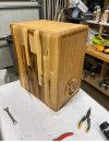
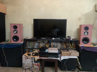
Time for another DIY Speaker project

@captrajesh
I think you needn't worry too much about the published specs being closer or away from measured specs. I don't know much about the tolerances of Dayton. But still since this speaker in its kit form has been made available by experienced designers, they might have thought about the matter and might have made necessary leeway. Anyway, a few hertz to the above or below the actual tuning might not make much difference audibly.

I don't know this 'tuning by the ear' method. To me, the easiest way to check box tuning/alignment is to either make an impedance measurement and identify the rough minimum impedance point between the impedance peaks (in a bass reflex alignment) where the impedance phase also simultaneously goes to zero. REW can be used for it and an impedance jig can be made out of a few connectors and a dual channel sound card on a PC. https://www.roomeqwizard.com/help/help_en-GB/html/impedancemeasurement.html

Another more accurate method is to do a nearfield measurement of the driver in the box and identify the notch around the tuning frequency. For example in the attached pic here: https://www.hifivision.com/threads/audibility-of-port-resonances.85679/, around 38Hz is the bass reflex tuning frequency as shown by the deep notch around this frequency

Thanks
Vineeth
 
I don't know this 'tuning by the ear' method.
For tuning by ear, one would need to experiment by varying port length's by as little as 0.25" or 0.5" between listening sessions because even that makes audible changes to bass. Anything else is a compromise which, IMO, is unnecessary! :D
 
Last edited:
<snip>
Considering that the original boxes are kept aside, no harm in trying especially since you have spare material available.
I will not try the laminate material. It is very difficult to work with.
But may consider ply with double side veneer, if I have enough spare wood left.
Lets see what pans out.

Cheers,
Raghu
 
For a 34 Hz box tuning in a 24 liter box, with a 3" ID port - the port length is 17.15 inches
Yup this looks about right my mental approximation was 16" ("If you replace a 2" dia. port with a 3" dia. port the length will be much too long for the box itself. The length is a factor of the area so the overall resultant port length would be 16" or so."). I am glad that your measurements are so close to that approximation. It gives me some confidence in what's left of my old, senile, demented brain.

One option to fit a 17" port would be to fire the port downwards and have the port run the height of the loudspeaker. I did this for a pair of Morel 8N515s in 1988 (with Dennis Ouellet at Solen Electronique, Quebec). It works quite well especially if you support the port about midway.
I had simultaneously emailed @navin advani seeking his advise on the issue. In his reply, the port length is exactly similar to the dimensions given by you.
I have always used LMS (from LinearX) or MLSSA (DRA Labs) to measure drivers (Morel, Focal, Eton, SEAS, ScanSpeak, etc.) but the method described by Vineeth Kumar below (using impedance curves) is also good enough at least to ascertain box alignment.

FYI there are many cheaper options like CalSod and Clio available (see links). I am sure that in the past 20 years (since I last measured drivers myself) there are many cheaper options. I heard good things about WinSpeakerz too.
@captrajesh
I think you needn't worry too much about the published specs being closer or away from measured specs.
I don't know this 'tuning by the ear' method. To me, the easiest way to check box tuning/alignment is to either make an impedance measurement and identify the rough minimum impedance point between the impedance peaks (in a bass reflex alignment) where the impedance phase also simultaneously goes to zero.
Yup this is indeed a usable method. But you have to build a box. If you have measuring software you can measure in free air and then build a box that is closer to the final result.
For tuning by ear, one would need to experiment by varying port length's by as little as 0.25" or 0.5" between listening sessions because even that makes audible changes to bass. Anything else is a compromise which, IMO, is unnecessary! :D
1/2" is close enough. You'd be hard-pressed to tell the difference just by listening beyond a variation of 1/2".

Capt. Rajesh, remember that companies like KEF, B&W, Monitor Audio, etc build 1000s of pairs of loudspeakers. Given the complexity of an acoustic suspension system, it is rare for 2 drivers to measure exactly the same yet if you check 2 pairs you will find them to be indistinguishable. Some companies do make matched pairs but that's an arduous process of finding drivers that measure about the same.

Sorry, I am not very conversant with social media and forums so I don't log on very often. You can email me to log on (send me a link) if and when you believe I can help.
 
One option to fit a 17" port would be to fire the port downwards and have the port run the height of the loudspeaker. I did this for a pair of Morel 8N515s in 1988 (with Dennis Ouellet at Solen Electronique, Quebec). It works quite well especially if you support the port about midway.
That, regrettably, might not be possible in this design since it has the open back mid cavity extending horizontally from front to back. Also, if not done right, the area between the speaker bottom and the surface it is elevated on becomes part of the port and loads it, thus making a hash of the design.

There is another uncommonly used way we can achieve what is needed wrt to tuning the box to what is desirable. It involves building a "PowerPort" originally patented by Polk. My gut says it is achievable. All it needs is some application of mind. And MS Excel. And the help of @Vineethkumar01.
 
Last edited:
That, regrettably, might not be possible in this design since it has the open back mid cavity extending horizontally from front to back. Also, if not done right, the area between the speaker bottom and the surface it is elevated on becomes part of the port and loads it, thus making a hash of the design.

There is another uncommonly used way we can achieve what is needed wrt to tuning the box to what is desirable. It involves building a "PowerPort" originally patented by Polk. My gut says it is achievable. All it needs is some application of mind. And MS Excel. And the help of @Vineethkumar01.
I can try to help. If we go down the Polk-type power port path, we would need some reference regarding how to build one. Augerpro's site has some info but not in much detail. At the moment, I don't know much details about the power port dimensions-based box tuning method.

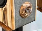
A simpler solution that just came to mind is this: If the current hole cut in the cabinet for the port is too large why not close it with a circular MDF piece such that it closes the existing circular hole for the port when it is stuck to the box from outside. Also one can pre-drill a sufficient sized hole to allow fitting it with the original port with dimensions specified by the designers. The circular MDF piece may also be rounded at its edges for smooth looks. Please see the attached pics for the idea. in the pic, the binding posts are attached through the circular piece. Here it can be substituted by the port with the original dimensions. The very small volume increase that this might cause to the box is immaterial to the overall scope of the project, I think.

PC: The pic, i have copied from Javad Shadzi's Helios CM build and other new builds
 

Attachments

  • Screenshot_20220304_125312.jpg
    Screenshot_20220304_125312.jpg
    823 KB · Views: 51
  • Screenshot_20220304_130057.jpg
    Screenshot_20220304_130057.jpg
    351.8 KB · Views: 50
Last edited:
I can try to help. If we go down the Polk-type power port path, we would need some reference regarding how to build one. Augerpro's site has some info but not in much detail. At the moment, I don't know much details about the power port dimensions-based box tuning method.

A simpler solution that just came to mind is this: If the current hole cut in the cabinet for the port is too large why not close it with a circular MDF piece such that it closes the existing circular hole for the port when it is stuck to the box from outside. Also one can pre-drill a sufficient sized hole to allow fitting it with the original port with dimensions specified by the designers. The circular MDF piece may also be rounded at its edges for smooth looks. Please see the attached pics for the idea. in the pic, the binding posts are attached through the circular piece. Here it can be substituted by the port with the original dimensions. The very small volume increase that this might cause to the box is immaterial to the overall scope of the project, I think.

PC: The pic, i have copied from Javad Shadzi's Helios CM build and other new builds
I might be wrong but I do not think the problem is fitting a port. That can be managed. The issue is that there is no Precision Port used and with regular ports, the length of the port for the desired tuning is 17.5" which will not fit given that the internal available depth of the box is only 10". A way out is to have part [10"] of the port sticking out of the box but I don't think it will pass the aesthetic test though if executed well, it can be made good looking with an angled port like a chimney. :cool:

I can try to help. If we go down the Polk-type power port path, we would need some reference regarding how to build one. Augerpro's site has some info but not in much detail. At the moment, I don't know much details about the power port dimensions-based box tuning method.
See attachment. Now you know! :cool:
 

Attachments

Last edited:
I might be wrong but I do not think the problem is fitting a port. That can be managed. The issue is that there is no Precision Port used and with regular ports, the length of the port for the desired tuning is 17.5" which will not fit given that the internal available depth of the box is only 10". A way out is to have part [10"] of the port sticking out of the box but I don't think it will pass the aesthetic test though if executed well, it can be made good looking with an angled port like a chimney. :cool:
The length issue comes with the 3 inch diameter port right?
I was trying to see if we can go with the original 2 inch diameter port itself with the modification that the 2inch port is now fixed on the added circular piece glued to the outside. :D

See attachment. Now you know! :cool:
Awesome. Thanks for this. This port calculator I am definitely going to study. :) :)
 
Last edited by a moderator:
Also, if not done right, the area between the speaker bottom and the surface it is elevated on becomes part of the port and loads it, thus making a hash of the design.
I thought Capt. Rajesh was using a flared port. I flared port wouldn't have the same challenges as a regular port.

The length issue comes with the 3 inch diameter port right?
Awesome. Thanks for this. This port calculator I am definitely going to study. :) :)
You could also have a slot for a port. Not all ports need to be round. They can be rectangular as well.

Besides ports can be folded with little detriment to the end result.

I do not have the T/S specs of the woofer but has anyone considered an aperiodic loading for this driver? Usually, drivers with very high Qtc fare well in this sort of cabinet.
 
@captrajesh
I think you needn't worry too much about the published specs being closer or away from measured specs. I don't know much about the tolerances of Dayton. But still since this speaker in its kit form has been made available by experienced designers, they might have thought about the matter and might have made necessary leeway. Anyway, a few hertz to the above or below the actual tuning might not make much difference audibly.

I don't know this 'tuning by the ear' method. To me, the easiest way to check box tuning/alignment is to either make an impedance measurement and identify the rough minimum impedance point between the impedance peaks (in a bass reflex alignment) where the impedance phase also simultaneously goes to zero. REW can be used for it and an impedance jig can be made out of a few connectors and a dual channel sound card on a PC. https://www.roomeqwizard.com/help/help_en-GB/html/impedancemeasurement.html

Another more accurate method is to do a nearfield measurement of the driver in the box and identify the notch around the tuning frequency. For example in the attached pic here: https://www.hifivision.com/threads/audibility-of-port-resonances.85679/, around 38Hz is the bass reflex tuning frequency as shown by the deep notch around this frequency

Thanks
Vineeth
For tuning by ear, one would need to experiment by varying port length's by as little as 0.25" or 0.5" between listening sessions because even that makes audible changes to bass.
That's precisely what he did. And said to have eliminated the boomy bass issue. I'm going to Calcutta for 4 days during which, I'll get it despatched to Mumbai. Can't carry it back as it may be too cumbersome and quite expensive too. Will update after reaching there.
I can try to help. If we go down the Polk-type power port path, we would need some reference regarding how to build one. Augerpro's site has some info but not in much detail. At the moment, I don't know much details about the power port dimensions-based box tuning method.

A simpler solution that just came to mind is this: If the current hole cut in the cabinet for the port is too large why not close it with a circular MDF piece such that it closes the existing circular hole for the port when it is stuck to the box from outside. Also one can pre-drill a sufficient sized hole to allow fitting it with the original port with dimensions specified by the designers. The circular MDF piece may also be rounded at its edges for smooth looks. Please see the attached pics for the idea. in the pic, the binding posts are attached through the circular piece. Here it can be substituted by the port with the original dimensions. The very small volume increase that this might cause to the box is immaterial to the overall scope of the project, I think.

PC: The pic, i have copied from Javad Shadzi's Helios CM build and other new builds
There are easier ways to close the port and it won't even show up.
I might be wrong but I do not think the problem is fitting a port. That can be managed. The issue is that there is no Precision Port used and with regular ports, the length of the port for the desired tuning is 17.5" which will not fit given that the internal available depth of the box is only 10". A way out is to have part [10"] of the port sticking out of the box but I don't think it will pass the aesthetic test though if executed well, it can be made good looking with an angled port like a chimney. :cool:

See attachment. Now you know! :cool:
Any link as to where this would be available!?
I thought Capt. Rajesh was using a flared port. I flared port wouldn't have the same challenges as a regular port.
Yes, flared port it is. Could you elaborate on the challenges or rather lack of it!
 
I have been DIY speakers past 10+ years, but till date could never figure out the tuning by ear method. Even my own speakers which is currently completed my design and assembly is from this week on fine tune mode now. But i don't know from where to start my fine tune without my simulations and measurements.

Imo, only the most talented and experienced DIYers can tune by ear.
 
From what I can see, all of you are speaker-DIY-addicts, too, so it is only a matter of time before you get there :) There will come a time/project/spare cabinet where motivation & curiosity intersect and you will do the experimenting. Very-much recommended on large cabinets. It is just trading-off damping and shaping the resonant bandwidth and response to the sound you like (and comparing to impedance and sims).

Congrats @captrajesh, it sounds like your project succeeded. You should have a fine speaker when you get it! It is neither the first nor last speaker with an oversized cabinet opening that required a recovery :)
 
Congrats @captrajesh, it sounds like your project succeeded. You should have a fine speaker when you get it!
Yeah, looks like it but as the old adage goes, proof of the pudding is in eating.
It is neither the first nor last speaker with an oversized cabinet opening that required a recovery :)
You seem to have something interesting to share.
 
Not really interesting, just honest and old. There are better tools now for hobbyists and info is much more accessible now. Changing wood was both viable and more-efficient when we had to live by voltmeters and hand-measure and hand-plot points. It's a really, really good time for a speaker diy-er to be alive now. Seriously, which would you rather do for 2-3 hours--change real ports and listen or wire-up & sit and measure voltages and manually plot points on paper? Everybody of a certain age learned to save port cut-outs in case they needed to use them as plugs later :)

And yes, you might not like how your new speaker sounds, but it should do a lot right. I like your project and didn't know of the Monitors variant until your thread. Hopefully it arrives safely and you have much enjoyment discovering what your new speaker does in your own space and with your own gear and music. Thank you for sharing your project. Please post updates if you feel inclined to do so.
 
Check out our special offers on Stereo Package & Bundles for all budget types.
Back
Top