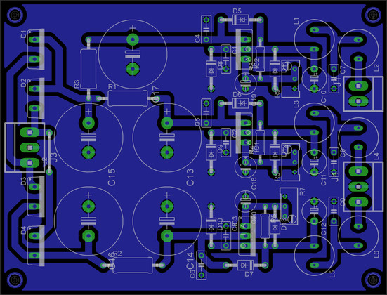
DCB1 Build

ok.. thanks for clarification...

while the resistors are procured i could dig couple of TO-220 heat sinks and attached to the two LM317s .. I have observed LM337 also getting hot.. does it also require a heat sink or R3 also require change? In my setup, my SSP requires 10V (OPAmp LM49990 based) and source selector 15V. So i am powering dcb1 and ssp from 10-0-10 output and Source selector 0-15v.

Kindly validate and advise..

Yes, 337 also need heatsink. I hope you changed resistance R2 also which supplies to LM337. BTW SSP + DCB1 is same line 2X DCB1. So use 250 ohm/2W in place of R1/R2.

Tame down 24V to 15V okay for SS. Small heatsink will be okay. No need to replace R3 if using only SS.
 
Last edited:
Yes, 337 also need heatsink. I hope you changed resistance R2 also which supplies to LM337. BTW SSP + DCB1 is same line 2X DCB1. So use 250 ohm/2W in place of R1/R2.

Tame down 24V to 15V okay for SS. Small heatsink will be okay. No need to replace R3 if using only SS.
Thanks..
I am yet to change R1 and R2..running in default components with heat sinks as of now..
 
That regulators may go to thermal shutdown or reduced life. Also Hi temperature has raised noise - figure beyond recognition of ears but measurable on scope. :)

LM317/337 can deliver 1.5A with proper dissipation of heat. But here we can kill it within 20mA (.02A) only. Reducing gap between input and output voltage is the key with small piece of Aluminum L shape attached to it. Look like cobra shape staring at front.

Thanks Om, also I am running the +/-10 for DCB1,SSP and CNC. As per your suggestion changed the voltage of 24v to 15v for the source selector. So for all the three which are using the +/-10 should I change the resistances on the PS as per your advice.
 
Thanks Om, also I am running the +/-10 for DCB1,SSP and CNC. As per your suggestion changed the voltage of 24v to 15v for the source selector. So for all the three which are using the +/-10 should I change the resistances on the PS as per your advice.

+/-10 for DCB1,SSP and CNC.

What are the chip counts in the CNC+SSP? if using all 49990 then use below formula.
For 1 dual OPAMP chip (count 1) replaced with 2X 49990 (count 2).

Current = (<num_of_ICs> * 0.01)+ (<num_of_DCB1> * 0.02)
resistance value = 10/(Current) ohms
consider 2W-3W for resistance value, plus small aluminum piece for each regulator.
 
Last edited:
+/-10 for DCB1,SSP and CNC.

What is the chips in the CNC+SSP? if using all 49990 then use below formula.
For 1 dual OPAMP chip (count 1) consider 2X 49990 (count 2).

Current = (<num_of_ICs> * 0.01)+ (<num_of_DCB1> * 0.02)
resistance value = 10/(Current) ohms
consider 2W-3W for resistance value, plus small aluminum piece for each regulator.

Yes Om I am having 2 of 49990 for CNC and 1 for SSP, I was using the stock opamps earlier but changed it yesterday with 49990 lying with me since more than 6 months. The calculation is greek and latin to me :o so please suggest what I need to change and where with how much value. That will help my life easier. Thanks in advance.
 
@Om: I'm going to take out the B1 board from Rikhav's cabinet and replace it with the DCB1. There are no other boards inside powered by the OPS. Do I still need to make the mod to the OPS?

Secondly, my cabinet will have the B1 and DCB1, both powered by the same OPS. Do you think I need to make the suggested OPS mod?

Will flower heatsink help the LMs?

PS: the B1 from my cab may also eventually go.
 
Yes Om I am having 2 of 49990 for CNC and 1 for SSP, I was using the stock opamps earlier but changed it yesterday with 49990 lying with me since more than 6 months. The calculation is greek and latin to me :o so please suggest what I need to change and where with how much value. That will help my life easier. Thanks in advance.

each position of 49990 in your described case are actually 2 chips on adapter, one visible and another below adapter. So you have 6 chips in total.

Current = 6 * 0.01 + 1 * 0.02 = 0.06 + 0.02 = 0.08A

Resistance = 10/Current = 10/0.08 = 125 ohm, (2W safe)
 
@Om: I'm going to take out the B1 board from Rikhav's cabinet and replace it with the DCB1. There are no other boards inside powered by the OPS. Do I still need to make the mod to the OPS?

Secondly, my cabinet will have the B1 and DCB1, both powered by the same OPS. Do you think I need to make the suggested OPS mod?

Will flower heatsink help the LMs?

PS: the B1 from my cab may also eventually go.

Yes, for load of 10V/-10V, please modify it.

For 1X DCB1 = 500 ohm, 2W
For 2X DCB1 = 250 ohm, 2W
For DCB1 + SSP = ~330 ohm, 2W <- (no 49990 mod)
For DCB1 + SSP + CNC = 200ohm, 2W <- (no 49990 mod)

For single DCB1+ 1 X SSP (with 49990) = 200 ohm, 2W
For 1 X DCB1 + 1 SSP (with 49990)+ 1 CNC (with all 49990) = 125 ohm, 2W

For 1 X DCB1 + 1 X CNC = 250 ohm, 2W <- (no 49990 mod)
For 1 X DCB1 + 1 X CNC = 160 ohm, 2W <- (with 49990 mod)

Nearby values with 10-20ohm will do, no problem.
 
Last edited:
@Om: I count three 1R resistors in the OPS board. Do we swap all three?

Swap ones which are parallel to each other and marked R1, R2. They are in direction from input to output of PCB, parallel to PCB's length.
preamppsbrd.png
 
Last edited:
Made the 500 Ohms mod for the OPS. The pin of the 3 Watt resistor I got was way too big for the pin hole of the board so I ended up fixing it from the bottom of the board. An extra riser was used to avoid the resistor scrapping the cab bottom. Checked the +/-10V voltages and there was no change from earlier calibration.

So Rikhav's DCB1 is completed. DC offsets are -0.35mV and -0.65mV. The DCB1 is sounding good, as usual:)

PS: even after extended use, I didn't notice any heat on the MUR810 or the pair of LMs, but still changed the resistor as advised by the designer. To be obedient is better than to be sorry later:)
 
Last edited:
Completed conversion of my DCB1 from double decker back to a single.

Also made the OPS resistor mod.

Fitted a two-source selection switch (a DPDT). I went the purely passive path as I can live with two sources (but not one:)). Thanks Om for verifying my source selection wiring diagram. I chose to fit the switch on the rear panel to reduce wiring length (though the lengthy pot wiring mostly nullified the gains achieved).

Now I can put the cover back and get back to listening to music:) The tiny board sitting alone in the middle of a vast and empty cabinet looks a bit comical.
 
Last edited:
Can we also share in the comedy? Pictures?

The cabinet cover was removed for very long time due to the incessant tweaks. I closed it only last night. But you're in luck;) I'm going to carry out the mod Om suggested in post # 6. After all, who doesn't want a sexier, throatier, huskier, sultrier and fuller female vox?:)
 
Does the DCB1 requires burn-in? I feel sometimes the highs are little harsh for my taste when compared to B1. I am yet to replace the resistances as suggested by Om and I should be doing it by this weekend. I rechecked the connections today and found one of the power cables loose on the DCB1 which I redid and now the crackling sound has gone but still the highs are little harsh and cracking type on the vocals especially. The bass is good and tight in comparison to B1. Not sure whether I am the one who is feeling it or does somebody else also have the same feeling.
 
DCB1 needs some burn in. Give it about 25-30 hours. Keep it always on even when you're not listening.

Highs should be crystal clear.

The OPS resistor mod will not affect your sonics. It is only for safety and longevity of the components.
 
I'm going to carry out the mod Om suggested in post # 6.

Carried out this mod. Used two 4700uF/25V electrolytics (Samwha). Haven't had the time to listen yet. I think the caps will need burn in. Pics later.
 
Does the DCB1 requires burn-in? I feel sometimes the highs are little harsh for my taste when compared to B1. I am yet to replace the resistances as suggested by Om and I should be doing it by this weekend. I rechecked the connections today and found one of the power cables loose on the DCB1 which I redid and now the crackling sound has gone but still the highs are little harsh and cracking type on the vocals especially. The bass is good and tight in comparison to B1. Not sure whether I am the one who is feeling it or does somebody else also have the same feeling.


Which power amp, speakers you have? Because I found it neutral, so we can find reason for your feeling. May be you listen few things more which weren't present earlier.
Power supply decouple caps 100uF, 0.1uF are important role for this. Verify those for polarity and connection.
 
Last edited:
Which power amp, speakers you have? Because I found it neutral, so we can find reason for your feeling. May be you listen few things more which weren't present earlier.
Power supply decouple caps 100uF, 0.1uF are important role for this. Verify those for polarity and connection.

I am using the ACA as the power amplifier with DIY Frugal Horn speakers. The same combination which I was using with B1. I am using the stock power supply along with the R-Core which I was using with B1. I am yet to replace the resistances that you/Sachin suggested on the power supply as it was running hot in most of the cases. I am listening to some of my frequent songs which I keep for references and hopefully it should settle in. When you say power supply decouple caps 100uF,0.1uF you are talking about the same on the power supply board right and not on the DCB1?
 
Purchase the Audiolab 6000A Integrated Amplifier at a special offer price.
Back
Top