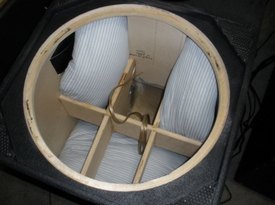
@Vineethkumar01 this is the draft. I will incorporate
@keith_correa simpler bracing scheme or a version of it.
View attachment 71833
Now that changes the sealed box bass alignment a tiny bit. This is because a 15inch driver will take up about approx. 5litre of space and your bracing too will take up a bit of space (I have assumed that it too takes up 5L of space) This is going to give you about 95L internal volume effectively. A bass alignment like this can give the following frequency response (solid blue line) compared to this driver in a cabinet with 105L effective internal volume (dot-dash line). This is not bad. It may even be a little better in terms of power handling (you will be able to put in a little bit more power in the 95L cabinet compared to a 105L cabinet)
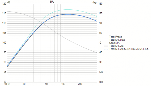
First thing that is new here is that now I have added the effect of rising inductance at higher frequencies caused by the driver's motor system (due to the lack of shorting rings in the motor). This is causing the droop down in response after 150Hz. However one will still be able to hit reasonably high SPLs as shown in the figure from 30Hz to greater than 200Hz with some EQing (if at all needed). So it is ok.
Here are some frequency response decay numbers (frequencies at which SPL is 3dB down from the max value (f3) , 6dB down from max value(f6) , and 10dB down from max value (f10))
Values for the105L cabinet
f3 48.3 Hz
f6 35.6 Hz
f10 26.3 Hz
Values for the 95L cabinet
f3 49 Hz
f6 36.2 Hz
f10 27.1 Hz
Notice the teeny tiny bit of loss in low frequency extension with 95L cabinet compared to 105L cabinet. This is typical. The advantage with 95L cabinet is that you may be able to put in about 20-30W more power into the system (this will help with frequency response shaping using EQ)
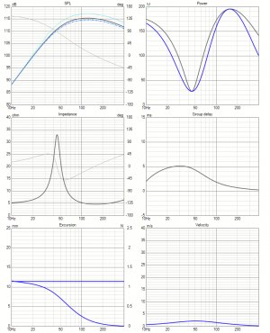
Here are more detailed results for the simulation above for those interested.
Now here is the impact on box resonance mode distribution for your cabinet dimensions as per the drawings
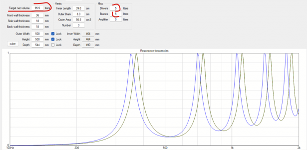
Notice how the green and red box modes have now collapsed into one single peak close to 400Hz compared to two more separated out modes in my previous posts. This will mean that there will be relatively strong box mode and impedance bump somewhere above 350Hz. The audibility of it will depend on the SPL levels, damping used inside the box and the upper frequency cut off used for the sub. If you intend to roll of the subwoofer around 120Hz or so or even lower, This may not be an issue. Still a thing to keep in mind..

Please do estimate the volume with bracing added. The lower the box internal volume is going to be, the more it will start to move into the "booming" regime. Ideally, with this sub you may not want to reduce the internal volume of the cabinet much further.
Cabinet construction detail-wise, do keep in mind that the driver has an outer diameter of about 420mm. Double thick baffle as you have drawn is a good idea. I prefer to have bracing interconnecting all panels of the box together. Especially the baffle to the back of the box, as the baffle is where most of the forces are going to be exerted. This is why I liked the initial bracing scheme. If you are going for a simplified bracing and going to put bracing only in the middle, please do take this aspect also into consideration. The forces exerted by a driver of this size on the baffle is not trivial and is better considered in the design stage itself in my opinion.
If you look at the elaborate bracing scheme, you will see that the scheme "braces" it at unnecessary (ineffective) places, IMO.
You mean the middle of the panel is where the forces/velocity modes are at their minimum and having the brace connecting all the middles of the panels may not be as effective as it looks like?
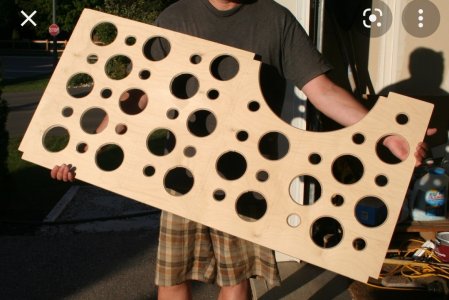
Now, to address the division part. Is it really dividing it? To really divide it, the brace needs to be a "holey" brace.

Ok. Would this kind of bracing be good?
similar to the simplified bracing shown above but located offset from the middle inside thr box. Also having something connecting the fromt baffle and back of the box
