New Design, SE 6005 Directly Coupled Audio Amplifier

Status
Not open for further replies.
1-1-2022 ................................ Wire Management of your own AUDIO SYSTEM......................................................

Several times in the last 14 months I have been on H.F.V., I have enthusiastically referred F.M.s to Mapleshade Audio's web page entitled " Wire Management ". Excellent advice there. Look it up and follow along as much as you can.

Sadly, the person behind Mapleshade, the capable and brilliant Pierre Sprey, died in late 2021. We do not therefore know, how long his web pages will be kept intact on line. Absorb it now !!

I just today found one additional web page, that mirrors my experiences - and makes MUCH sense to me. Pierre, R.I.P, was right on the money, in every way .


I would like to also share this wire information with the appropriate interested audio enthusiasts. Here it is :

Copy it and save these notes on your hard drive !!


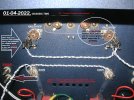
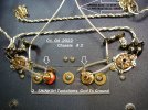
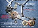
I also want to show people the first 2022 audio purchase, I made - just one hour ago. It is 100% related to wire management !!

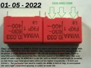
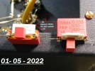
View attachment 65790View attachment 65792View attachment 65793

Just enough glass insulators ( 4 ) for the positive and negative polarities, not to ever touch each other, nor the floor or carpeting, ... and for both channels. A new, permanent DIY solution, .............is coming up !!

Jeff

PS : Ohh my goodness, Pierre nailed it ....... wonderful reinforcement .......... 9.52 feet in a speaker lead, and ALSO in an AC Power cable, sounded better to my audio mentor Dennis, than a single ( 4.76 feet ) Robert Fulton length !!!!!

Based on my records and the cables and interconnects that I still have, I know that 57.2" is the nominal reference length of the RCA-RCA interconnects that Fulton was selling, and that the speaker cables that he was selling were integral multiples of that nominal length. But I don't recall Fulton ever recommending 57.2" (equivalently 4.76') or its integral multiples as the best lengths for a power cord. So, I was wondering if you have a reference to anything that Fulton ever published which specifies a recommendation for the best/optimum lengths of a power cord.
 
Based on my records and the cables and interconnects that I still have, I know that 57.2" is the nominal reference length of the RCA-RCA interconnects that Fulton was selling, and that the speaker cables that he was selling were integral multiples of that nominal length. But I don't recall Fulton ever recommending 57.2" (equivalently 4.76') or its integral multiples as the best lengths for a power cord. So, I was wondering if you have a reference to anything that Fulton ever published which specifies a recommendation for the best/optimum lengths of a power cord.
What is the significance of 57.2" ? We are talking about base band audio, right? The electrical half wavelength of 20khz is 24600 feet!
 
What is the significance of 57.2" ? We are talking about base band audio, right? The electrical half wavelength of 20khz is 24600 feet!

I have no idea how Fulton's 57.2" reference length for RCA-RCA interconnects and speaker cables came about.
Bob Fulton was Jeff Medwin's mentor, not mine. So I suggest that you ask him.
 
01-04-2022 ........ Mini Photo REPORT ...........................Filament WIRING now IN PLACE

Much more to do, AUDIO section now, stereo chassis TWO, ( as opposed to basic Power Supply. ) A neat start.

Filament wiring, old fashioned finger - thumb twisted carefully, and not with an electric drill.

005 EDITED.jpg


In December, I purchased four ( !! ) Ott-Lite model L-1399s, which allows anyone to see inside the internals of a build much much better than before. I would highly recommend this product, to DIYers or anyone seeking good, natural spectrum lighting. Look it up, on line, fantastic history, lovely product - Dr. Ott. A++. Seeing well, what you are doing, immediately improves one's execution. This is the experience so far !!
 
Last edited:
01-04-2022 ........ Mini Photo REPORT ...........................Filament WIRING now IN PLACE

Much more to do, AUDIO section now, stereo chassis TWO, ( as opposed to basic Power Supply. ) A neat start.

Filament wiring, old fashioned finger - thumb twisted carefully, and not with an electric drill.

View attachment 65831


In December, I purchased four ( !! ) Ott-Lite model L-1399s, which allows anyone to see inside the internals of a build much much better than before. I would highly recommend this product, to DIYers or anyone seeking good, natural spectrum lighting. Look it up, on line, fantastic history, lovely product - Dr. Ott. A++. Seeing well, what you are doing, immediately improves one's execution. This is the experience so far !!

Is there some reason other than cost and simplicity to AC power the filaments? It seems to me that If the filaments were DC powered from a well filtered and hard regulated supply, any noise that is on the AC line would be totally eliminated and bandaids like hash chokes would not be needed in an attempt to clean up what should not even exist in the first place.
 
What is the significance of 57.2" ? We are talking about base band audio, right? The electrical half wavelength of 20khz is 24600 feet!

After a bit of searching and some luck, I came across a post dated Jan 3, 2018 in HiFiHaven by dowto1000 (aka Jeffrey Medwin).
An excerpt from that post is as follows:

"I met RWF in 1978 at a Audio Seminar he gave at Mission Bay Audio in San Diego, at Dr. Tom Johnson's store. RWF explained that the University of Minnesota Psychology Lab had been audio-testing baboons, at high frequencies in the 10 to 20 kHZ range. " Stimulus - response ". The University's tests were lengthy, scientific, and well-documented.
When the Lab upped the audio signals from 20 kHZ to 60 kHZ, all these well-documented baboon subjects got SICK, and very confused. They called in a local-to-them audio recording engineer, Robert W. Fulton, and it was RWF's job to see why the animals were not reliably responding, so as to continue on with the Lab's experimental work.
Robert, at the seminar, explained, he measured the audio amplifier's frequency and phase response, at he amp's output terminals, at 20 and 60 K. It was fine. He next measured the same things at the loudspeakers' input terminals, and while the frequency response was reasonable, the phase response was badly shifted. The problem, he deduced, may be in the connection, between the amp and the speaker, ie : the speaker's connecting wire.
RWF always had a great home lab, and was a genius at measuring audio events. In his lab, he developed all the parameters for a wide band speaker cable, that would not shift phase at 60 kHZ, and be suitable for the baboons and the University. One part of the new cable's design parameter, Francis, was that RWF determined that 57 1/8th inches was the best overall audio " compromise length "."

Clearly, something was lost by dowto1000 in translation because it is not possible for a speaker cable having any practical finite length to have zero phase shift at 60kHz. Perhaps the realistic and sensible objective was to achieve a zero deviation from linear phase at 60kHz. Unfortunately, Fulton is no longer among us, so we will never know, and the above clearly nonsensical explanation is probably the only one that exists.


If, Robert Fulton, your mentor, actually claimed that "an inch of bad wire can RUIN the Musical Experience", that's good to know. But, the more important practical question is did Robert Fulton ever share with you what type(s) of wire should be avoided and what type(s) are needed to be used in order to preserve the musical experience? If he did and if it isn't a secret, I'm sure that many readers in this forum would be interested in the knowing.
 
01- 05 -2022 ............ A small COMMENTARY , a CRITIQUE on INPUT SIGNAL WIRING ....................................


In this world, about 99 percent of the audio amplifiers we see built, ( in my opinion ) place the RCA Input jacks in the wrong position on the chassis.

Where DO they get put? Why on the rear vertical portion of the chassis, so that there is a uncluttered and neat look to the front of the amplifier. It matters not, if the amp is inexpensive or costly, aspires to a budget price or to be of the best possible fidelity, .... the RCA jacks are placed in the REAR!!!

Realize this, the music signal coming into the audio amplifier is the lowest signal level in the entire amplifier. As such, it is subject the MOST, to wire-losses, and stray fields interacting ( and polluting ) the purity of the music's signal.

Common sense here. You just have to exercise independent thought !!

What fields does the INPUT RCA jack "see" when located on the back vertical panel?? Usually, and always unfortunately, often the largest most destructive fields in the entire amplifier !! This is so sad.

First, there is the field of the AC powering the unit, 120 VAC or 230 VAC typically, which generates a huge field. Would you lay an input interconnect on a power cord ??? Or put an interconnect cable anywheres near a 230 VAC power cord.? Relax, the amplifier's mis-designer, has already done this for us, by design - in 99% of the amps, ..... to " look neat ".

The second horrendous thing the input cable " sees " is the large fields developed by the unit's power transformers and power supply...or perhaps the output transformers. These parts are usually in the rear of a unit, and the Input signal cable has to pass by them, and their fields. Oh my, ..........the input signal is subject to degradation there from ANY magnetics that are actively energized, powered "on".

The third problem seen, with a rear entry RCA jack, is the long DISTANCE. The fragile signal has to go the furthest, to reach the Input stage, where it activates the amplification process.

IT IS ..........." RCA jack on the rear panel, Input tube at the front of the amp."

Isn't that " the way it usually is "??? Well, this causes the fragile input signal to transverse a large distance, rear to front, by design.

We are taught in textbooks and in schools, to keep component wiring as short as possible. It is the Gospel. Rear RCA jack entry is JUST the opposite of this !!! But WAIT a minute, it gets much worse.

To sell audio equipment to the unknowing public, Manufacturers, ( and the majority of unconscious DIYers ), will make these long wire runs " below deck " look NEAT, by bundling and TIE WRAPPING the Input wires together, left and right channel. Sometimes with OTHER wiring, running in the same direction.

EVERY tie wrap inside an amplifier, degrades the integrity of the music's signal
. You did not know this?? Well now you do . ( Mapleshade / Pierre Sprey ).

There is a natural field around each and every single signal wire in an amplifier. A tie wrap interrupts that wire's field, an energy field !!

Tie wrapping two or more wires having unlike potentials, both together, is even worst. When you bundle multiple wires tightly together, their differing fields interact with each other. Phooey !!

It is the equivalent of putting a blanket, heavy wool, over your woofer , midrange, and tweeter. Common sense here, no college degree needed. Again, if you have been oblivious, you can pick up some decent wiring tips, and learn from the Mapleshade /Pierre Sprey pages that have been repeatedly referred to. Internalize his suggestions !!

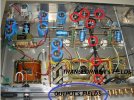
To show you all. Below is a used French JADIS "integrated " power amp, that my good friend bought a month or two ago. Current version in the USA sells for around $13,000.

View the two shielded black-colored INPUT signal wires, the distance they run, and the fact that are not separated, ( the left channel's field from the right channel's field ). Worst of all, look at the tie wraps, I have circled in red. Each and every one of them, should never have been applied, and the two channel's wires should have been separated, well....by at least 1/8th an inch.

Those few trollers, critical of me, will say " it is an integrated, and it has to be that way. I would be SHOCKED if their non-integrated amps, are built any different !!


.............2 JADIS TIE WRAP- EDITED 2.jpg


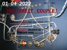
Now look at the double Wonder Wired short distances of the 6005 DC amp's input wiring, earlier photographed.. The conscious decision to use doubled-up Wonder Wire is to optimize signal transfer efficiency , minimize wire losses, yet retain wide bandwidth.

Jeff
 
Last edited:
I wonder what sort of effect the plastic outer jacket on a electrolytic capacitor has.... Or the paint used on resistor markings. Do light photons interact with fields through ventilation holes? After light is electromagnetic radiation too....maybe that's why music sounds better with the lights off.
I wonder, I wonder. I wonder how I sleep with all.this spinning around in my head.
 
I am now starting to believe "silence is bliss". Atleast I don't have to worry about anything that's inside and outside the hood :)-
 
01- 05 -2022 ............ A small COMMENTARY , a CRITIQUE on INPUT SIGNAL WIRING ....................................


In this world, about 99 percent of the audio amplifiers we see built, ( in my opinion ) place the RCA Input jacks in the wrong position on the chassis.

Where DO they get put? Why on the rear vertical portion of the chassis, so that there is a uncluttered and neat look to the front of the amplifier. It matters not, if the amp is inexpensive or costly, aspires to a budget price or to be of the best possible fidelity, .... the RCA jacks are placed in the REAR!!!

Realize this, the music signal coming into the audio amplifier is the lowest signal level in the entire amplifier. As such, it is subject the MOST, to wire-losses, and stray fields interacting ( and polluting ) the purity of the music's signal.

Common sense here. You just have to exercise independent thought !!

What fields does the INPUT RCA jack "see" when located on the back vertical panel?? Usually, and always unfortunately, often the largest most destructive fields in the entire amplifier !! This is so sad.

First, there is the field of the AC powering the unit, 120 VAC or 230 VAC typically, which generates a huge field. Would you lay an input interconnect on a power cord ??? Or put an interconnect cable anywheres near a 230 VAC power cord.? Relax, the amplifier's mis-designer, has already done this for us, by design - in 99% of the amps, ..... to " look neat ".

The second horrendous thing the input cable " sees " is the large fields developed by the unit's power transformers and power supply...or perhaps the output transformers. These parts are usually in the rear of a unit, and the Input signal cable has to pass by them, and their fields. Oh my, ..........the input signal is subject to degradation there from ANY magnetics that are actively energized, powered "on".

The third problem seen, with a rear entry RCA jack, is the long DISTANCE. The fragile signal has to go the furthest, to reach the Input stage, where it activates the amplification process.

IT IS ..........." RCA jack on the rear panel, Input tube at the front of the amp."

Isn't that " the way it usually is "??? Well, this causes the fragile input signal to transverse a large distance, rear to front, by design.

We are taught in textbooks and in schools, to keep component wiring as short as possible. It is the Gospel. Rear RCA jack entry is JUST the opposite of this !!! But WAIT a minute, it gets much worse.

To sell audio equipment to the unknowing public, Manufacturers, ( and the majority of unconscious DIYers ), will make these long wire runs " below deck " look NEAT, by bundling and TIE WRAPPING the Input wires together, left and right channel. Sometimes with OTHER wiring, running in the same direction.

EVERY tie wrap inside an amplifier, degrades the integrity of the music's signal
. You did not know this?? Well now you do . ( Mapleshade / Pierre Sprey ).

There is a natural field around each and every single signal wire in an amplifier. A tie wrap interrupts that wire's field, an energy field !!

Tie wrapping two or more wires having unlike potentials, both together, is even worst. When you bundle multiple wires tightly together, their differing fields interact with each other. Phooey !!

It is the equivalent of putting a blanket, heavy wool, over your woofer , midrange, and tweeter. Common sense here, no college degree needed. Again, if you have been oblivious, you can pick up some decent wiring tips, and learn from the Mapleshade /Pierre Sprey pages that have been repeatedly referred to. Internalize his suggestions !!

To show you all. Below is a used French JADIS "integrated " power amp, that my good friend bought a month or two ago. Current version in the USA sells for around $13,000.

View the two shielded black-colored INPUT signal wires, the distance they run, and the fact that are not separated, ( the left channel's field from the right channel's field ). Worst of all, look at the tie wraps, I have circled in red. Each and every one of them, should never have been applied, and the two channel's wires should have been separated, well....by at least 1/8th an inch.

Those few trollers, critical of me, will say " it is an integrated, and it has to be that way. I would be SHOCKED if their non-integrated amps, are built any different !!


.............View attachment 65849


Now look at the double Wonder Wired short distances of the 6005 DC amp's input wiring, earlier photographed.. The conscious decision to use doubled-up Wonder Wire is to optimize signal transfer efficiency , minimize wire losses, yet retain wide bandwidth.

Jeff
You state that "There is a natural field around each and every single signal wire in an amplifier". But, that is only true for the case of a single, unshielded conductor. In the case of a coaxial cable, such as the parallel black cables that are tied together in the picture that you show, the field outside of each coaxial cable is zero. Consequently, your statement that the "tie wrap interrupts that wire's field' is incorrect, and that's because it isn't possible for the tie wrap to interrupt a field that doesn't exist.
 
I wonder what sort of effect the plastic outer jacket on a electrolytic capacitor has.... Or the paint used on resistor markings. Do light photons interact with fields through ventilation holes? After light is electromagnetic radiation too....maybe that's why music sounds better with the lights off.
I wonder, I wonder. I wonder how I sleep with all.this spinning around in my head.
Yes, it's quite difficult to grasp the sad truth isn't it?

Look at how far we have come in electronics. Our cell phones, tablets, self driving cars, and yet after now 100 years of practice and learned knowledge, only a retired businessman and a potato farmer in Montana know how to build an audio amplifier properly! If only their genius could have been applied to other fields of science.

Just imagine where we would be today?
 
Is it so difficult to be kind to others?
That's a good question, and one that you and others who are reading this thread, including the moderators, should be asking JDM.
In case you don't get the point, here are just a couple of examples that are representative of the sort of arrogant and condescending remarks for which he is well known and which have gotten him banned from virtually every audio forum on the internet.

Post #219: "Knowing things technically, certainly does not mean you are any good at all in audio, and that you approach audio " playing with a full deck ". Dr.Gary comes to my mind actually, L.O.L., all his life, as THE PERFECT example of this."

Post #250: " I was only attempting to reinforce my position, and real-life findings of over half a century in audio, to make-up of for the thread's dilution, caused by others, ( people with much education, and with a university background. )"

Post #250: Overall, I would guess 90% of the amplifier builders and designers I have met and known over the years, do not come from University Research or E.E. degreed backgrounds. In fact, like some of this thread's very recent posters : most EEs and university people are at a distinct and VERY OBVIOUS disadvantage, compared to say, me, with a degree in Business Administration.
 
01 - 05 -2022 .............. Mini PHOTO REPORT........Today's Cathode Resistor and BYPASSING work ...............


Hello everyone, thank you for looking today !!!


007  EDITED FULLY.jpg


023  EDITED DATE.jpg


035  EDITED FULLY.jpg

.........................................................Below, STEREO AMP IMPLEMENTATION for TODAY's work...............................................................................


036 edited.jpg


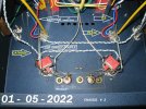
All the four tubes' Cathodes now have DOUBLE WONDER WIRE soldered carefully in place, on their tube socket Pins, and they are ready to transfer energy efficiently - and in a superb fashion. This is a simply a total attention to a build's details, with higher audio performance, being the sought-after goal.

Tomorrow we get to work on the STAR GROUND system, and the Rk power resistors ( on the large Black Colored heatsink) for the amp's two Output tubes.. Slowly but surely !!

Jeff
 
Last edited:
SIMPLY IGNORE THEM ........ REALLY GOOD ADVICE !! ......... WELL SAID.


nwwdlw​

12:01 AM (4 hours ago)
to me


Thanks for the update. Your work is superb as usual.

Looking at the latest EE arrogant rebuttals on your thread makes me realize they cannot see beyond their trained view. Which is usually narrow. That they cannot seem to take your experience and effort as an exercise in thought, a gift.

One would think instead of arguing on their limited view. They would be experimenting at least to debunk your claims. They are closed based on their expert discipline as an EE. Which qualifies them as knowing more about your work than you do without hearing it. Or, experimenting with your methods????????

Damn arrogant know it alls if you ask me.

That is why I dropped away from the forums. I got Sick of the arrogance.

I hope you ignore them. Teach the ones who will listen.


NW
 
Status
Not open for further replies.
For excellent sound that won't break the bank, the 5 Star Award Winning Wharfedale Diamond 12.1 Bookshelf Speakers is the one to consider!
Back
Top