Hi Friends
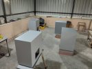
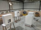
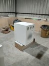
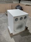
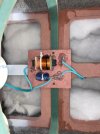
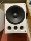
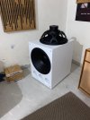
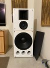
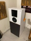
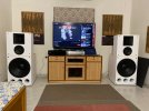
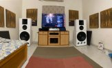
I am back with another Project, a 3-Way design with P A Drivers again. This time also its all Beyma drivers. 18 Inch Sub, 8 Inch Mid & Ribbon Horn Highs (TPL 150). All drivers are Neo Magnet. The Bass Enclosure will be separate, The Mids & Highs will be in separate enclosure.
As usual I have modeled the enclosure in 3D software (Solid Edge ST6) so that I can get the exact volume which is required as per design.
I am not writing too much on the enclosure design. I will be sharing the built process. So below are the photos of same.
Panels cutted on CNC
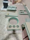
Even though all panels are cut on CNC, Remember the CNC also has its own tolerance error. A table saw can be very useful when you need to flush the panel my 1 mm or 2mm.
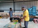
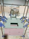
Front Baffle is double 25 mm HDMMR (HDF) total 50 mm thick, Glued with each other & clamped.
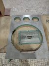
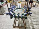
Getting the Frame ready, Sides Top & Bottom. These are screwed with each other,
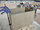
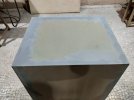
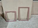
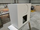
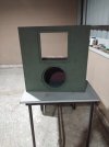
Front face of Mids & Highs Enclosure
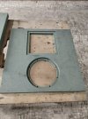
Assembly of Bracing in Bass Enclosure
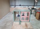
Felt used for lining internal walls of Bass Enclosure
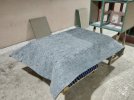
Gluing of Felt with internal walls with fevicol (Marine). I forgot to mention the glue I am using is Fevicol Marine grade
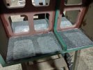
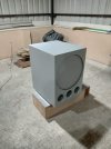
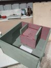
Mid Enclosure assembly
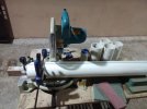
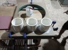
Vents Cutting & Gluing. I am using Finolex schedule 40, A 4" Pipe for vents. It is very thick and very strong. This Pipe diameter is big for my Miter Saw so i have to make 2 passes to cut the pipe throughout.
And here is my new toy again "Makita RP2301FC" Router to make the Round-over on the Vents. Its a very Powerful Router with 3.25 HP of Power. The coll-et size is 12 mm. It has variable speed so I can control the speed, this feature is very useful while using big diameter bits. This Router is Beast, I didn't feel any load on this machine, it was running like a hot knife on Butter. It is also very heavy but when using it, it was very steady and very comfortable. The Plunge mechanism was the Best among the routers which i have used till date.
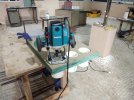
The Radius of round-over is 19 mm. It just took 2 passes to get the job done. It is very difficult to do this radius with lower power rated routers.
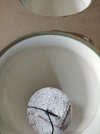
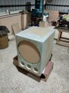
Assembly of Front Baffle, In Front Baffle I have not used screws, Its just glued, However the Back Panel is screwed with Sides Top & Bottom.
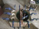
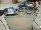
After gluing today I did sanding, The HDMMR sheet is very hard I had to use belt sander to sand the edges and then Orbital sander for smooth finish, After sanding I patched the holes of screws with sawdust and glue.
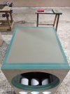
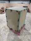
This is the built journey till today. I will update this thread as i progress further.
I am back with another Project, a 3-Way design with P A Drivers again. This time also its all Beyma drivers. 18 Inch Sub, 8 Inch Mid & Ribbon Horn Highs (TPL 150). All drivers are Neo Magnet. The Bass Enclosure will be separate, The Mids & Highs will be in separate enclosure.
As usual I have modeled the enclosure in 3D software (Solid Edge ST6) so that I can get the exact volume which is required as per design.
I am not writing too much on the enclosure design. I will be sharing the built process. So below are the photos of same.
Panels cutted on CNC

Even though all panels are cut on CNC, Remember the CNC also has its own tolerance error. A table saw can be very useful when you need to flush the panel my 1 mm or 2mm.

Front Baffle is double 25 mm HDMMR (HDF) total 50 mm thick, Glued with each other & clamped.


Getting the Frame ready, Sides Top & Bottom. These are screwed with each other,

Front face of Mids & Highs Enclosure

Assembly of Bracing in Bass Enclosure

Felt used for lining internal walls of Bass Enclosure

Gluing of Felt with internal walls with fevicol (Marine). I forgot to mention the glue I am using is Fevicol Marine grade

Mid Enclosure assembly


Vents Cutting & Gluing. I am using Finolex schedule 40, A 4" Pipe for vents. It is very thick and very strong. This Pipe diameter is big for my Miter Saw so i have to make 2 passes to cut the pipe throughout.


And here is my new toy again "Makita RP2301FC" Router to make the Round-over on the Vents. Its a very Powerful Router with 3.25 HP of Power. The coll-et size is 12 mm. It has variable speed so I can control the speed, this feature is very useful while using big diameter bits. This Router is Beast, I didn't feel any load on this machine, it was running like a hot knife on Butter. It is also very heavy but when using it, it was very steady and very comfortable. The Plunge mechanism was the Best among the routers which i have used till date.

The Radius of round-over is 19 mm. It just took 2 passes to get the job done. It is very difficult to do this radius with lower power rated routers.

Assembly of Front Baffle, In Front Baffle I have not used screws, Its just glued, However the Back Panel is screwed with Sides Top & Bottom.

After gluing today I did sanding, The HDMMR sheet is very hard I had to use belt sander to sand the edges and then Orbital sander for smooth finish, After sanding I patched the holes of screws with sawdust and glue.


This is the built journey till today. I will update this thread as i progress further.


