New Design, SE 6005 Directly Coupled Audio Amplifier

Status
Not open for further replies.
OK, thank you so very much for the clarification !!! Please take some time, and study the Softone web site, as nicely detailed information on their audio output transformers is provided. They also offer an R-Core Interstage, that is likely very good. You might enjoy seeing all of that, if you have not already done so. Reasonable prices exist.

Best wishes,

drlowmu
 
Last edited:
IIRC, Audio Tekne probably used R Core output transformers in the past. No idea if they still use them. Their new stuff says Permalloy transformers but does not say anything more
 
Thanks for your comments... informative.

When you say
" It has much lower distortion than all the others, due to it's intrinsic R-Core design. It " lures" the listener into the music, and plays melodically in a way that I think is impossible - for a non R-core."

Is the lower distortion comment purely subjective ?

Or have you made measurements ?

Hi IndianEars :

Here below, we see a article written in 1998, addressing the two Ohm imbalance between the two wound halves of an E-I power transformer's high voltage winding. ( 38 Ohms and 40 Ohms .) The author developed a unique method, to reduce the distortion this caused, and he shows us his measured graphs of the difference in lowered distortion, in dB.

Realize this, a R-Core has the secondary wound on a separate bobbin, by computer, in a balanced DCR ( and maybe even balanced in capacitance and inductance, I need to check this ) manner. So, the R-Core's design would avoid this distortion problem to start with !!!

The 800 VCT at 450 mA. power transformer that Hari and I had wound at Shilchar Technologies last year for his KT-88 SE build, has not a 2 full Ohm difference between halves. Hari measured only a 0.1 Ohm difference, between winding halves.

In 2021, I properly AC orientate every single AC connection, individually by a scope and or by ear is possible, in my tube amplifier builds. A tube amp is not ever optimized ........until this gets done.

I hope this information becomes meaningful, helpful, to you, and to other DIY FMs :

 
Last edited:
Thanks, drlomu. Good Info.

A bifilar wound primary on an EI transformer should also solve the problem.

As I have mentioned earlier, I too am a fan of R Core Transformers, as mains transformers.

P.S: Which Rectifier tube do you use in yr current design ? The post mentions an interesting option to use a Directly heated Rectifier tube to elegantly resolve this problem. Of course attention needs to be given when using directly heated rectifiers, since they fire up very quickly.....
I now prefer to use dual rectifier tubes, from 2019 on.

Two types : either Electro Harmonix 5U4GB, an inexpensive current tube, very " peppy " sounding with decent balance, made in USSR, or vintage GE 5U4Gs, black plate with a round mica top and a non-hanging filament . Nice sounding, but not as long lived.

We now have a custom design for a new R-Core 5 VCT / 6 A. filament transformer, which I know will make an audible difference with directly heated rectifiers.

In my preferred type of ultra low DCR, and low uF power supply, I like the directly heated rectifier's instantaneous response, VS: a cathode type rectifier.

You next, need to listen to, experience a Softone RW-20 in a good SE amplifier. Nothing I am aware of, even remotely compares to that output transformer, after a break in.

IndianEars,

I forgot to explain this : the currently available Electro Harmonix 5U4GB takes about 75 hours when new, to break in and to sound it's best.

I did not truly understand your earlier post's comment. I am an amateur, and have many gaps in my E.E. knowledge. Really !! ( LOL, often this is to my advantage, because I will try " crazy " things, others will not !! )

Please explain, how does a bifilar wound primary correct for a two Ohm DCR imbalance on two halves of a High Voltage secondary winding ?? How does that work ?? How common are bifilar wound primaries ?? Is that difficult to wind on an EI core ??? Who does that now, commercially ??

Sorry for all the questions. It is one way for E.E. amateurs like me, and other FMs, to learn !

PS,

I am ordering five more pairs of Softone RW-20 R-Core SE outputs tomorrow, air-shipped, for my nicest audio friends to own / use.

drlowmu
 
Last edited:
IndianEars,

I forgot to explain this : the currently available Electro Harmonix 5U4GB takes about 75 hours when new, to break in and to sound it's best.

I did not truly understand your earlier post's comment. I am an amateur, and have many gaps in my E.E. knowledge. Really !! ( LOL, often this is to my advantage, because I will try " crazy " things, others will not !! )

Please explain, how does a bifilar wound primary correct for a two Ohm DCR imbalance on two halves of a High Voltage secondary winding ?? How does that work ?? How common are bifilar wound primaries ?? Is that difficult to wind on an EI core ??? Who does that now, commercially ??

Sorry for all the questions. It is one way for E.E. amateurs like me, and other FMs, to learn !

PS,

I am ordering five more pairs of Softone RW-20 R-Core SE outputs tomorrow, air-shipped, for my nicest audio friends to own / use.

drlowmu
drlowmu, my filament Transformer for my driver tubes 6.3v center tapped @3 A is a Bifilar winding EI Transformer made by Silachar Transformer. The bobbin is split in 2 half - horizontally probably 60/40. One half carries the primary winding and other secondary.
 
Hammond Ef Transformers use a similar split, but I am not sure it is bifilar wound. Need to look that up. EZ to do.

An R-Core should be superior.

Question : Why are you using a 3 A. power transformer, for a 600 mA. load??

Question : Have you ever measured the Ef VAC at the 6FQ7 tube socket pins Hari ?

Your line is already abnormally high these days !! What do you measure for the 6FQ7 input tube's Ef in VAC ??? The spec is 6.3 VAC plus or minus 0.6 VAC. It is best to have it close to 6.3 VAC for long term use. There are two ways to accomplish this, no......... three.

1) use a Ef XFR rated close to your load. Not 3 A.

2) use hash chokes, on each EF Pin of your tube socket, sufficient in current rating to power the filament, and of adequate DCR so as to lower the VAC closer to a nominal 6.3 VAC. This is a superior design technique, because you also minimize unwanted power transformer noise at a input tube, even if the tube is indirectly heated as they usually are.

3) use resistance ( a wire wound power resistor) in the Ef transformer's wiring, in series to the load. When using a dedicated totally separate Ef XFR, ( which is usually an improvement - IF phased properly ) never add resistance to the secondary. It will always sound best applied to the XFR's primary winding !!!

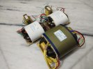
Off topic, what was the second ( smaller ) R-Core XFR's rating and use, that you photographed below, for each mono KT88 amplifier? Was it for use only for the 5U4GB dual rectifiers ?? If so, that is fabulous. A highly audible sonic improvement to a good tube amp such as yours. It is exactly what I intend to have made up. Recall the Shilchar $USD cost, prior to shipping ?? 30 VA core?? 5 VCT at 6 A. ???

BTW, I believe it is properly .......... Shilchar Technologies !!

IMG-20200811-WA0022  PHOTO R-Cores.jpg
Hari Iyer's Transformers photograph .


Thanks,

drlowmu
 
Last edited:
drlowmu said
"Please explain, how does a bifilar wound primary correct for a two Ohm DCR imbalance on two halves of a High Voltage secondary winding ??"

My typo, I was referring to the High Voltage winding with the unbalanced DCR.

Obviously, Bifilar windings will correct unbalance between those windings only.

drlowmu, you said:
"Two types : either Electro Harmonix 5U4GB, an inexpensive current tube, very " peppy " sounding with decent balance, made in USSR, or vintage GE 5U4Gs, black plate with a round mica top and a non-hanging filament . Nice sounding, but not as long lived."

I think Both these rectifiers are Directly Heated.

As mentioned in the last para of that tentlabs linked article from Electronics World (Earlier Wireless World, a superb publication in its day) that you posted:

"If your power supply has a directly-heated rectifier, there may be no need for all that. Simply reverse the heater leads to get about 15dB improvement. There is a 50:50 chance that they were the wrong way round."

Hence using an E I core transformer with unbalanced winding DCR should not cause you any problems. When an R Core transformer is used in such a location, it solves a non existent problem (with Directly heated rectifiers) as long as you have flipped the heater leads and checked.
Yes IndianEars, I read this same thing also : "If your power supply has a directly-heated rectifier, there may be no need for all that. Simply reverse the heater leads to get about 15dB improvement. There is a 50:50 chance that they were the wrong way round."

I do not think this is the case. If the High voltage windings' DCR halves are imbalanced, can you explain to me, why this might be so, other than someone writing it as such in an article.

I do know, from my personal and direct experience, that AC polarities must be correct !!!!!

As of mid-2019, I AC orientate every AC connection, on the primary and the secondary, in any SE tube amp I build. I discovered ..... it is necessary - if one seeks quality in performance.

For the record, my audio mentor of the last three decades, whose judgement I trust fully, does not like the sound of transformers with bifilar windings.

drlowmu
 
Hammond Ef Transformers use a similar split, but I am not sure it is bifilar wound. Need to look that up. EZ to do.

An R-Core should be superior.

Question : Why are you using a 3 A. power transformer, for a 600 mA. load??

Question : Have you ever measured the Ef VAC at the 6FQ7 tube socket pins Hari ?

Your line is already abnormally high these days !! What do you measure for the 6FQ7 input tube's Ef in VAC ??? The spec is 6.3 VAC plus or minus 0.6 VAC. It is best to have it close to 6.3 VAC for long term use. There are two ways to accomplish this, no......... three.

1) use a Ef XFR rated close to your load. Not 3 A.

2) use hash chokes, on each EF Pin of your tube socket, sufficient in current rating to power the filament, and of adequate DCR so as to lower the VAC closer to a nominal 6.3 VAC. This is a superior design technique, because you also minimize unwanted power transformer noise at a input tube, even if the tube is indirectly heated as they usually are.

3) use resistance ( a wire wound power resistor) in the Ef transformer's wiring, in series to the load. When using a dedicated totally separate Ef XFR, ( which is usually an improvement - IF phased properly ) never add resistance to the secondary. It will always sound best applied to the XFR's primary winding !!!

Off topic, what was the second ( smaller ) R-Core XFR's rating and use, that you photographed below, for each mono KT88 amplifier? Was it for use only for the 5U4GB dual rectifiers ?? If so, that is fabulous. A highly audible sonic improvement to a good tube amp such as yours. It is exactly what I intend to have made up. Recall the Shilchar $USD cost, prior to shipping ?? 30 VA core?? 5 VCT at 6 A. ???

BTW, I believe it is properly .......... Shilchar Technologies !!

View attachment 55294
Hari Iyer's Transformers photograph .


Thanks,

drlowmu
If I recall correctly, my VAC was 7.2v no load. I used a common mode choke and a 0.47 ohm , 6 watts WW resistor on each leg to bring that voltage to 6.4v. what should be the wattage / value of the resistor if I need to put that in primary instead of secondary? Alternatively I can also used two diodes reverse connected to drop 0.7 volts in each leg.

The big Transformer in the photo is not mine but belong to a friend. The white coloured Transformer is my main transformer that has 3 taps 400v, 5v, 6.3v. The EI Transformer is my driver filament heater.
 
drlowmu said
"For the record, my audio mentor of the last three decades, whose judgement I trust fully, does not like the sound of transformers with bifilar windings."

Is this for output transformers only or also for Mains / Power transformers ?
 
If I recall correctly, my VAC was 7.2v no load. I used a common mode choke and a 0.47 ohm , 6 watts WW resistor on each leg to bring that voltage to 6.4v. what should be the wattage / value of the resistor if I need to put that in primary instead of secondary? Alternatively I can also used two diodes reverse connected to drop 0.7 volts in each leg.

The big Transformer in the photo is not mine but belong to a friend. The white coloured Transformer is my main transformer that has 3 taps 400v, 5v, 6.3v. The EI Transformer is my driver filament heater.
Dear Hari:

Why don't we keep this off - topic material out of this 6005 build thread ?

Email me and we can hash out your KT88 amps' filament needs and implementation.

You will not typically put resistances on primaries, unless the XFR is dedicated to just one filament winding.

I have additional questions, as to what you have done.

Since early 2020, we no longer power the 5 VAC rectifiers from the main plate transformer. The main XFR's B+ winding inter-modulates the rectifier's winding, under dynamic conditions. It is easily best sonically, to use a phase - aligned separate Ef XFR for directly heated 5U4GBs. All the build schematics provided, shows that.

Also, as you now do, we prefer to use dual 5U4G rectifiers, wired each as a single diode.

drlowmu
 
Last edited:
Dear Hari:

Why don't we keep this off - topic material out of this 6005 build thread ?

Email me and we can hash out your KT88 amps' filament needs and implementation.

You will not typically put resistances on primaries, unless the XFR is dedicated to just one filament winding.

I have additional questions, as to what you have done.

Since early 2020, we no longer power the 5 VAC rectifiers from the main plate transformer. The main XFR's B+ winding inter-modulates the rectifier's winding, under dynamic conditions. It is easily best sonically, to use a phase - aligned separate Ef XFR for directly heated 5U4GBs. All the build schematics provided, shows that.

Also, as you now do, we prefer to use dual 5U4G rectifiers, wired each as a single diode.

drlowmu
Ok. Noted.
 
3-28-21 ..... MINI UPDATE ..... WITH NO SEXY PHOTOS
Quite unusual, two near-retirement age audiophiles are having me to build a copy of my new Direct Couple tube amp, for their own use. It is the first time I am ever doing such a thing. In all the decades of my amp building, it was always " for my own use ", not for resale.

I found that double series shunting the B+ to critical areas of the amp, was not quite good enough, fidelity wise. What does work to my extreme satisfaction is a four section filter topology to these sensitive areas. This takes extra parts ( it takes an L/C and L/C in series, two additional sections, placed before the two SHUNTS in series ).

One of the changes we will all see, will be to the prototype chassis seen so far, in this thread. It's size will be enlarged by two inches side to side, 1 ¼ inches front to back, and 3/8ths of an inch in depth. All the re-dimensioning will allow parts to fit inside reasonably well. I will have to rebuild my own amp, and now, two additional. Fine.

Three other of my trusted longtime audiophile friends want to DIY build this circuit, so I am now responsible, in one way or another, for six of these DC 6005 SE stereo amps.

Saturday, 3-27-21, a dozen Softone RW-20 SE R-Core output transformers were International Air Priority FEDEX shipped to me, from Yokohama, Japan. Happy news.

Two weeks ago, I finalized the circuit design with the Softone RW-20 output transformers in place. I have the Direct Couple exactly where I want it ( voltage and current-wise ). Both tubes are operating individually and jointly as one optimized “ centered ” circuit. Many pages of measurements, for each small resistor value change, documented what was found eventually to be ideal. When you change a resistor value in a directly coupled amplifier, many things change !! The amp will operate and track nicely over varying line input voltages, and the tubes will long-term operate conservatively and reliably.

I have decided to make my main B+ power transformer a custom R-Core, as well as the filament transformer for the stereo amps' double 5U4GB tube rectifiers. These two R-Core power transformers will offer several unique advantages, with sonic consequences. ( Lower distortion ). As soon as I obtain the core sizes from the custom R-Core winder, I will have precise dimensions to specify a new chassis.

Now I plan to have all six chassis plasma cut, of heavy 14 gauge steel, including holes for the tube sockets, the transformer mounting, and ventilation / cooling holes. Each chassis will have four welded corners, and be powder coated.

This 6005 stereo directly-coupled amplifier is intended for my personal long term use, on ALTEC VOTT A7-8 speakers. That always was ….. the original intent.

This DIY amplifier design is unique in many ways. Allow me to spell them out to you please, so you might understand.

1) Use of lower distortion custom R-Core transformers, for the power supply and the output transformers

2) Use of dual and directly-heated tube rectifiers

3) Use of two-in-series six Ohm low DCR power supply chokes ( L1/C1/L2/C2 ) to the Finals

4) Use of two 1,500 Ampere capable GTO power supply caps, for razor-sharp / leading edge transient delineation.

5) Use of film caps throughout, and fully-developed multiple film cap bypassing in critical locations

6) Use of extensive wire lead augmentations, with wire having silver content

7) Use of three separate phase-aligned power transformers, for the B+, the tube rectifiers' ( a big deal ) and driver tubes' filaments

8) Use of a two-stage directly coupled circuit. A Russian 6N23Pi into a USA beam tetrode 6005. Detente..... in 2021.

9) Use of no Negative Feedback with a tetrode Finals stage amplifier, and short silver-content wire paths

10) A separate driver and separate G2 B+ supply with passive quadruple R/C filters, and shunt filters, in series ( an awesome thing ).

11) Use of conservative tube operating points, typically at 62% ( Golden Ratio ) or less of their maximum rated plate dissipations

12) Use of higher voltage driver tube operation, over 200 VDC on it's plate, ( at reduced current ) so the circuit swings the music's input signal voltage freely - with a certain unique sense of liveliness

13) Use of two tubes, selected such that their “ theoretical ” mu when multiplied, approaches 400. This is the best way we know, from our direct experience, to have a sense of “ jump factor ” in a tube amp's music presentation. An amp with a good " jump factor:" is more mentally involving to hear. It offers the uncanny sense of "You are there ", right at the original recording site, and hearing things in the real time of the music.

14) Use of a low-resonance 14 gauge all steel chassis, powder coated, with welded corners and an “ Isolation Platform ” engineered bottom cover.

15) Use of a 6005 tube, which has a symmetrical construction, a round plate, cathode, grid structure, tightly and symmetrically spaced to each another . ( without four corners, there are no “sneak feedback” electron paths possible ).

16) Use of resistor choices, proven already as being sonically desirable . Caddock, Roderstein, etc etc.

Because of all of the above ( 16 ) design factors, I fully expect the new amplifier design to play back music “ world-class ”, and to hopefully set new standards in one's listening, with high efficiency speakers.

No one has ever implemented a 6005 tube in this above manner !! All of this is the culmination of four decades of my own DIY tube amplifier building. It keeps me mentally motivated, to execute this as well as I can. This Single Ended tube amp should be a great deal of fun to hear and experience on 101 dB ( and above ) full range speakers !!

Thanks for your time today, for reading my laundry list - and allowing me the freedom of expression, to share my expectations . Time will tell. :)

drlowmu
 
Last edited by a moderator:
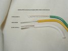
This excellent picture below, shows three leads. The middle one is the stock lead, from a reputable USA winder's transformer ( a Stancor ).

See how small the actual wire is? This is typical !!

Above and below it, are a 14 and 12 AWG lead of Mil Spec wire, multi stranded copper, each strand silver plated ( m22759/11 ). In all my DIY builds, I prefer magnetics' leads to be larger than stock, and made of this same Mil Spec wire, as photographed.

P1010044  EDITED 3-28-21.jpg

Lead augmentation subjectively enhances dynamics, dynamic contrasting, and bandwidth. One is paying attention to details, normally overlooked - by most who build audio equipment.

I always seek to design or re-build equipment thinking in terms of ........ "pulsed information, and instantaneous peak currents ".

Think about, for example, a drum kit solo recording, ( drums and cymbals )......... closely miked, or a concert grand piano heard live and close up..

drlowmu
 
Last edited:
PRACTICAL FOLLOW - UP

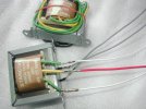
An hour ago, two new phono preamp Power Transformers ( dual mono ) were delivered to my door, by UPS. Within 15 minutes, I was cutting off the stock leads, on each's primary and secondary. All the stock leads were 22 AWG, and fairly nice wire.

I augmented each XFR's five leads, with three 16 AWG Mil Spec ( m22759/11 16 ) leads, and two ( white ) leads of 18 AWG. This should sound quite a bit better - more efficient coupling of energy, than 22 AWG !!!

Everyone relates visually :
009.JPG

005  EDITED.jpg
Above, is all pre-heat shrinking.

Below is the preamplifier, out of chassis, on the bench, for recent testing. This is a 1981 Robert Fulton / Nexus Engineering "Bravura" Dual Mono phono and line stage device. I am the original owner. Mr. Fulton was my first audio Mentor, 1978-1988.
Medwin_Bravura (1).jpg
Thanks for looking. I anxiously await hearing this modification. This will be fun to hear !!

Some of us use larger than stock power cords, and will swear by it. How about, after doing that, the obvious wire path, into and out of the equipment's Power Transformers??

drlowmu
 
Last edited:
Some of us use larger than stock power cords, and will swear by it. How about, after doing that, the obvious wire path, into and out of the equipment's Power Transformers??

That's a subjective thing sir.

It may be logical but subjective all the same.

A thicker gauge power cord by itself doesn't make things better.

I find most things to be a compromise..one hardly gains something without losing elsewhere.

Here is a nice return ball lobbed into the air for you to smash !

15 : 0

:-))
 
That's a subjective thing sir.

It may be logical but subjective all the same.

A thicker gauge power cord by itself doesn't make things better.

I find most things to be a compromise..one hardly gains something without losing elsewhere.

Here is a nice return ball lobbed into the air for you to smash !

15 : 0

:))

You are 100% right !!! ..................... " Subjective ".

- - - - - - - - - - - - - - - - - - - - -

The thicker power cord will only sound better if all else in the system is up to snuff, properly installed, and optimized. Also, thicker wire has a lower bandwidth, so it better be designed to be thicker - and also have some silver in it, to widen it's bandwidth.

I do use 12 AWG copper multi-stranded and silver plated wire - for my Line Cords ( m22759/11 12 ).

- - - - - - - - - - - - - - - - - - - - -

We need to acknowledge and always remember this, not all things in audio can be measured, that are subjectively heard by us.

For example, do you know that we humans all can hear - through our eyes ?

It is easy to test, while attending a live ( purely- acoustic ) music event, ( or if I am in front of my ALTEC VOTT A7-8 speaker system. )

I am a senior citizen. If I take off my eye glasses, the music sounds better to me, slightly better- always.

When making critical evaluations of parts changes in my DC SET amps, I will now ( in 2021 I started doing this, with the new 6005 prototype DC SET amp ) always try to listen to amplifier circuit changes ................with my eyeglasses off my face !!

I am sure you would agree, I am making subjective evaluations, very subjective, as to a circuit change.

And I will ask you with a big smile on my face, " Has anyone ever measured what I am hearing ???? " Can they measure it ??? Are they even aware....... of what I am doing ????

If your music system is not up to snuff, one will need to do this test at a live unamplified-music event, while listening " close up ". " Eyeglasses off, eyeglasses on ". Which way does the saxophone, or the marching band positioned in front of you, sound the best, sound the most real ??

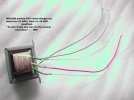
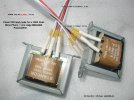
Here is what the leads from the dual mono preamp power transformers look like, after augmentation ( away from 22 AWG ) and after heat shrinking each leadout carefully ( to mainly stabilize and also insulate the joint.)

Now, XFRs are ready for installation. These XFRs will get rigidly mounted on multiple brass washers of differing outside diameters, forming a pyramid shape, and brass bolts and nuts, when installed into a steel chassis.

002 (2)  EDITED WELL 3.jpg


drlowmu
 
Last edited by a moderator:
Status
Not open for further replies.
Get the Award Winning Diamond 12.3 Floorstanding Speakers on Special Offer
Back
Top