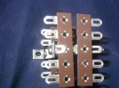
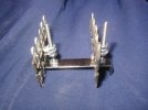
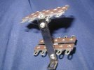
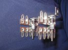
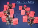
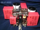
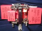
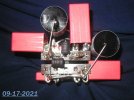
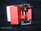
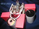
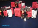
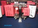
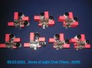
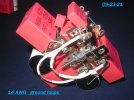
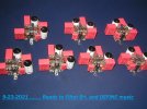
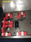
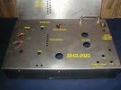
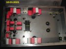
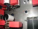
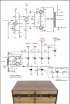
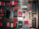
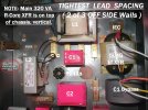
The power supply design topology outlined on 2-22-21 in this thread :
(
https://www.hifivision.com/threads/...tly-coupled-audio-amplifier.82963/post-929069 )
has been changed ( about 8-2021) to a ( hopefully ) better-performing design.
- - - - - - - - - - - - - - - - - - - - -
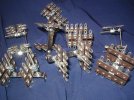
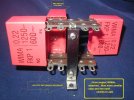
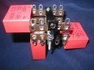
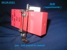
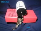
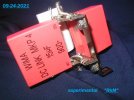
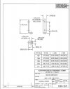
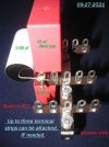
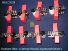
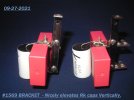
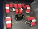
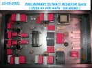
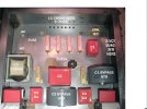
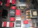
The latest design takes extra power supply parts. The two recently-developed build Modules, ( designed for this crowded stereo amplifier-
VAM and
RkM ) , will free-up chassis space for the new power supply topology - to be installed and accessed for service.
The two most sensitive areas of this amp is
the B+ feeding the plate resistor of the Input / Driver tube ( Ra ) , and (G2 ) the internal second grid of the Output Tetrode,. Both sensitive areas get the same design :
a quadruple sectioned passive filter. Let me try to show it with a typewriter !!
Note, both of these filter chains get fed from the last capacitor that feeds the Final's ( Output ) tubes (
"C2" ). First of all, allow me to show you that ( initial ) output stage topology :
Main B+ Power Transformer > dual tube rectifiers > Main L1-6 Ohms / Main C1 / Main L2-6 Ohms / Main "C2" ( to
both output transformers )
and to BOTH of the new quadruple filters, .........................
all fed from Main " C2 ".
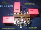
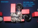
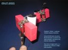
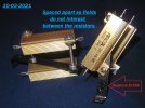
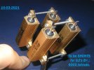
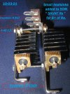
( each "quad" B+ filter is - effectively : SHUNT 1, SHUNT 2, L1-
one Ohm / C1
and L2-
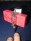
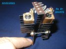
one Ohm / C2 ) . ( The L1 and L2 are those two tiny one Ohm hash chokes, seen on top of each
"VAM". )
Either will be like this : Here we are :
............................................................................
> Second SHUNT Left Channel
>( "
VAM" ) 15uF + L1 / C1 / L2 / C2
> ( feeds Ra Left ( or
G2 Left
)
Main "C2" > Pre
SHUNT One,
shared L-R ( split to each channel, see above and below )
..........................................................................
> Second SHUNT Right Channel
> ( "
VAM" ) 15uF + L1 / C1 / L2 / C2
> ( feeds Ra Right ( or G2 Right )
This above filter, fed by MAIN " C2" is built twice in the stereo amp, once for the Driver tubes' Ra, and once for the Finals' tubes' G2.
How confusing is my explanation? Please, only those F.M.s who can follow it, kindly leave a " thumbs up " or " like" at the bottom of this post. There may not be adequate room for all of the thumbs down . 
I am anxious to hear this. For the record, a usual tube amplifier would use one resistor and one cap, called a R/C decoupling section.
" In the end, we all listen to a modulated power supply....how good is it ? "
Jeff
