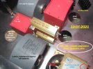
I am planning to add one 0.15uF, 630vdc Vishay MKP axial capacitor across my C2 to handle HF pulse to prevent them from reaching the KT88 grid2 or the driver plates. I already have a 5uF GTO and a 0.033uF, 800v EPCOS but the Vishay are very good at handling transient pulse.OK Hari, good point. Let us do this simpler than a shield.
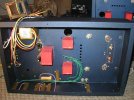
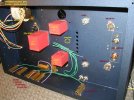
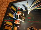
By removing the L2 choke off of the left vertical chassis wall ( Option 2 ) , and the 5U4G filament XFR off the right vertical wall ( Option 3 ) , we can relocate many 50 Watt ARCOLS on those vertical chassis wall spaces. The mounting spaces become "freed up" - on either side of the chassis.
I will consider doing this on 10-6, but only when I am fresh and rested. We shall call relocating the resistors " Hari's Option 4 ".
Since the Option 3 photo was posted, I have moved the C1 Bypass GTO to be 1/2 inch closer to the chassis center, and the L2 choke 1/2 inch away from the center, to lessen possible field interactions between these two large power supply chokes.
In our filtering, the first choke, L1, has large current spike fields associated with it. This is because it is ( on purpose, to get low DCR ) less than textbook " Critical Inductance " rated....( thank goodness ). L1 is a Hammond 159ZA, with a generous 1 Amprere current rating, so it does a fine job with current spikes in the L1 position after a break-in of 75 hours. However, the 159ZA's use requires there always be a similar L2/C2 topology in series with L1/C1. L1 and L2 must be the same to avoid audible skews. Finally, we certainly want a choke input filter - that a 5U4-type rectifier "sees", not a capacitor.
We always use two sections of filtering " L1/C1/L2/C2 " to the Output stage. As you have found out Hari, these 6 Ohm 159ZA chokes perform wonderfully, especially when we combine them with our use of GTO bypasses and really good wiring to the Output stage.
Thank you very much for helping .
Jeff
You are using an out of date browser. It may not display this or other websites correctly.
You should upgrade or use an alternative browser.
You should upgrade or use an alternative browser.
New Design, SE 6005 Directly Coupled Audio Amplifier
- Thread starter drlowmu
- Start date
- Status
- Not open for further replies.
10-07-2021 .............................. Mini REPORT, COMMENT
Designing and building your own DIY amplifier can become an amazing process, when it comes to laying out the internal parts.
Two days ago I posted three possibilities or " Options ". F.M. Hari Iyer suggested what became " Option 4 ".
I was dreading constructing individual "shelves or platforms", to raise each of four WIMA power supply capacitors off of a hot chassis floor. A lot of work, and time, for a minor embellishment.
Today, upon awakening, I realized now only two hot ARCOL 50 Watt resistors would be near the power supply's caps ( the others are now mostly on the side walls, as per me and Hari's Option 4 . )
A new idea instantly occurred.
Since space is tight, ( and these two ARCOLS will each be dissipating 2.9 and 3.2 Watts of power ), these can be mounted OFF the chassis floor, in free air with tiny / compact 10 Watt heat sinks added, on long 4-40 stainless steel threaded rods.
The two ARCOLS would " hover " vertically spaced apart and "over" each other - in the same ideal footprint-position ................which has already been determined.
( Recall, " build in three dimensions, not two ? " )
With six Watts less heat, ( and the two resistors no longer being chassis - cooled ) the power supply capacitors can now be attached directly to a cooler-running steel chassis floor. ............ No "platforms or shelves" required !!
- - - - - - - - - - - - - - - - - - - - - - -
What I wanted to share with you is, that sometimes ( often ! ) it takes several days, to come up with decent layout solutions. Usually, at the very beginning of one's day, when fresh and rested. new ideas come into our minds...." like lightning ".
Mounting the stacked / spaced apart two resistors on stainless steel threaded rods, above the chassis floor, was a truly very "happy " solution today.
Minimalist hardware and complexity........ just two long threaded rods, and several nuts for securing and positioning resistor heights. Elegant.
ARCOL HS Manufacturer's datasheet supplied below. ( FYI, a large ARCOL HS is a decent-sounding, OK to use power resistor IMHO ).
Pictures forthcoming, once executed.
Jeff
Attachments
Last edited:
Hi Jeff, build coming along nicely.
Will you be installing heatsinks as well?
Susnick
Hi Jeff, build coming along nicely.
Will you be installing heatsinks as well?
Susnick
Undecided until running and very scientifically finger tested........how many seconds can one hold their own finger on the part ?????
In datasheet posted above, a HS-50 Watt resistor shows " up to 14 Watts, with no heatsink, but ... at very elevated temperatures. "
Each HS-50 will be dissipating about 3 Watts.
These little sinks in the photo require a chassis backing surface. A slightly larger sink can employ the nuts on the threaded rods, to hold resistor to the mini sink, and that is what we need to find. Need a perfect size and shaped one...something ideal.
Heatsinks?? Well hello " Nebraska Surplus Sales " !! https://www.surplussales.com/sitemap2/alphalisting.html Click on " H ".
Jeff
Last edited:
Jeff,
These Arcol resistors get pretty hot imo. I have mounted 4 of them on my bottom aluminium plate and can actually cook bread on them literally. Efficient heat dissipation / distribution is most important for any amplifier. Do not worry much about how they will look internally as it won't matter. Thick about how you would couple them with the chassis for distributing heat.
These Arcol resistors get pretty hot imo. I have mounted 4 of them on my bottom aluminium plate and can actually cook bread on them literally. Efficient heat dissipation / distribution is most important for any amplifier. Do not worry much about how they will look internally as it won't matter. Thick about how you would couple them with the chassis for distributing heat.
keith_correa
Well-Known Member
Two small "U" shaped sinks. One stacked over the other with contact between them via bolts. The resistors mounted to the bottom valley area of each of the "U". The lower heatsink bolted to chassis.
You get the benefit of heat dissipation from the sinks and from the chassis too. Doable?
You get the benefit of heat dissipation from the sinks and from the chassis too. Doable?
Dear Hari,Jeff,
These Arcol resistors get pretty hot imo. I have mounted 4 of them on my bottom aluminium plate and can actually cook bread on them literally. Efficient heat dissipation / distribution is most important for any amplifier. Do not worry much about how they will look internally as it won't matter. Thick about how you would couple them with the chassis for distributing heat.
Each of your own KT88 monoblock amps is dissipating a total of about 20.56 Watts into that aluminum bottom plate. It is using only four power resistors. Yes, it will get very hot. Each ARCOL 50 Watt resistor in your amp averages 5.14 Watts of dissipation.
My all-steel chassis has at least twice the surface area of your KT88's single bottom plate.
This new stereo amp, ( with double shunting to all stages ) dissipates 39.5 Watts total.
The new amp's dissipation however, is spread over 13 different power resistors. This averages 3.03 Watts per device.
Of this new stereo amp's 39.5 Watts total, 14 Watts is dissipated by two paralleled "large-surface-area" black anodized heatsinks, ( seen in the middle of the chassis.) The chassis has been laser cut purposely - 14 ventilation holes below it, and seven above the black heatsink.
The stereo amp's remaining is 25.5 Watts ( 39.5 minus 14 ), is dissipated by the steel chassis' side walls.
All I am trying to do is relieve the chassis' dissipation on the floor of the chassis - near the supply caps, by re-positioning the two ARCOLS positioned close to the film caps, ( each resistor dissipating 2.9 Watts and 3.1 Watts. )
I think it is a reasonable idea, for the long term longevity of the power supply's film capacitors, to have these two resistors totally air cooled. As a precaution, I will add compact 10 Watt heatsinks to each. This will assist the resistors - from operating at needlessly high internal temperatures.
Fortunately, I have had adequate time to contemplate this execution.
Jeff
Last edited:
Two small "U" shaped sinks. One stacked over the other with contact between them via bolts. The resistors mounted to the bottom valley area of each of the "U". The lower heatsink bolted to chassis.
You get the benefit of heat dissipation from the sinks and from the chassis too. Doable?
But the fields of the two resistors will interact with each other. I want space between the power resistors, as per the photo. Thanks !!!
Jeff
keith_correa
Well-Known Member
I suggested that the 2 sinks be stacked over each other and not the resistors. There will be sufficient space between them.But the fields of the two resistors will interact with each other. I want space between the power resistors, as per the photo. Thanks !!!
Jeff
OK, I misinterpreted what you meant. Understood now.I suggested that the 2 sinks be stacked over each other and not the resistors. There will be sufficient space between them.
I actually will be using the two small heatsinks, partially shown in the right top corner of the posted photo. I will not have either device or it's heatsink touch the chassis, for reasons described in the response to F.M. Hari Iyer, above.
Your thoughts and kind contribution are appreciated. Thank you !
Jeff
PROGRESS REPORT .................... 10-12-2021
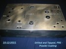
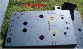
The 13 ventilation holes on the right side ( above ) , I added carefully by hand this week, as an afterthought to enhance long term cooling and reliability. Besides the added ventilation holes we see, the entire Main Chassis surface area acts to cool the internal components when using chassis - mounted ARCOL HS 50 Watt-rated resistors.
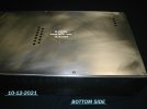
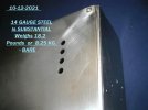
This above is the first ( of two ) chassis . It is finished as far as being ready to powder coat, Midnight Blue Wrinkle, with a Pearl glow.
What you see is the prototype, that I keep for myself. It has 23 " non used, non wanted " small holes in it, from changing parts positions to come across the " best " layout within my capability. The second unit ( now 90 percent prepared for Powder Coating ) is a bit " cleaner" looking - with 23 less non-essential holes . There will be an attractive and strong six inch handle at the very top-front of the chassis, and a matching four inch handle at the left side-top rear.
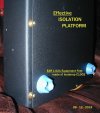
The bottom cover, held onto the Main Chassis by six 8-32 brass bolts, will have multiple brass washers, between the bottom cover and the Main Chassis. These brass washers will have varying O.D.s or outer diameters, such that they form a pyramid shape when secured. These six pyramids, and four soft "EAR " brand made-for-audio feet, form a " Isolation Platform " of the 14 gauge steel bottom cover, between the Main Chassis and the amp's resting surface. The pyramids allow for some all-around-the -bottom ventilation, and provide a benefit S.Q.-wise, and from vibration control, that the EAR feet used alone will not produce. This idea is copied directly from Serious Stereo's wonderful SET amplifiers, by me. I only build amps in a steel chassis, not wood, for fire-safety reasons, plus 14 gauge steel sounds good VS aluminum IMHO.
..................................
Both chassis should be ready for the Powder Coating shop, by the end of this week.
Thank you for looking.
Jeff

The 13 ventilation holes on the right side ( above ) , I added carefully by hand this week, as an afterthought to enhance long term cooling and reliability. Besides the added ventilation holes we see, the entire Main Chassis surface area acts to cool the internal components when using chassis - mounted ARCOL HS 50 Watt-rated resistors.


This above is the first ( of two ) chassis . It is finished as far as being ready to powder coat, Midnight Blue Wrinkle, with a Pearl glow.
What you see is the prototype, that I keep for myself. It has 23 " non used, non wanted " small holes in it, from changing parts positions to come across the " best " layout within my capability. The second unit ( now 90 percent prepared for Powder Coating ) is a bit " cleaner" looking - with 23 less non-essential holes . There will be an attractive and strong six inch handle at the very top-front of the chassis, and a matching four inch handle at the left side-top rear.
The bottom cover, held onto the Main Chassis by six 8-32 brass bolts, will have multiple brass washers, between the bottom cover and the Main Chassis. These brass washers will have varying O.D.s or outer diameters, such that they form a pyramid shape when secured. These six pyramids, and four soft "EAR " brand made-for-audio feet, form a " Isolation Platform " of the 14 gauge steel bottom cover, between the Main Chassis and the amp's resting surface. The pyramids allow for some all-around-the -bottom ventilation, and provide a benefit S.Q.-wise, and from vibration control, that the EAR feet used alone will not produce. This idea is copied directly from Serious Stereo's wonderful SET amplifiers, by me. I only build amps in a steel chassis, not wood, for fire-safety reasons, plus 14 gauge steel sounds good VS aluminum IMHO.
..................................

Both chassis should be ready for the Powder Coating shop, by the end of this week.
Thank you for looking.
Jeff
Last edited:
10-22-2021 .............................................. Photo Update
First two chassis just were returned from Powder Coaters. This conservative color is called " Midnight Blue Wrinkle" and it has a bit of pearl in it.
View attachment 63412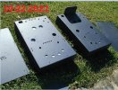
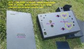
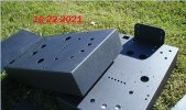
On Sunday, 10-24-21, twelve tube sockets got satisfactorily installed into both chassis. Final assembly is progressing now.
Jeff
First two chassis just were returned from Powder Coaters. This conservative color is called " Midnight Blue Wrinkle" and it has a bit of pearl in it.
View attachment 63412


On Sunday, 10-24-21, twelve tube sockets got satisfactorily installed into both chassis. Final assembly is progressing now.
Jeff
Last edited:
11-04-2021 ............................................. Mini PHOTO PROGRESS REPORT
Today, a dual ON-OFF AC switch system was installed. The first switch turns on the amp, and the second switch shorts-out the safety fuse, so the amp can pull maximum power from the Wall, when playing back music.
The second switch is called " an ATTENDED LISTENING " switch. It is illegal in a typical commercially manufactured product, but all my builds employ this to obtain better ( audibly better ) performance. This is especially noticeable with the type of Power Supplies ( Low in DCR, six Ohm chokes, etc. ) we find in my designs. The end-user gets to determine to employ, or not to emply the second switch, as the amp plays music either way.
In the last three years, we have found that separate multiple power transformers ( For B+, and separate for Filaments ) can give an audible performance edge. Importantly, we have also discovered that the AC phase of all the secondaries powering the circuit, MUST ALL be in phase-alignment with each other, to obtain the best sonic result.
The simple Keystone - manufactured terminal strip pictured below will provide adequate multiple attachment points ( NOT available on a tiny single FUSE's terminal ) , to allow doing an in-phase alignment of this amplifier's various secondary windings.
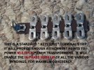
Below are the two A-C switches, the Fuse Assembly, and the Multiple AC attachment points to optimize phase relationships of the Power Transformers. Such steps are done because of the desire to optimize one's listening experience on music playback. It is the ONLY justification.
' Am building two amps at once, and tomorrow this gets done to the second stereo amplifier, plus more !!
Notice above how I have prepped the vintage NOS Amphenol Octal Rectifier tube sockets? They no longer have eight PINS sticking out. It is nicer to only have the four pins per socket, required for the 5U4GBs. I prefer the immediate instantaneous response of directly heated tube rectifiers.
Thank you - for looking.
Jeff
See how both sections of the AC switches are parallel wired ?
Also, for the first time ( for me ), the switch contacts on these AC switches are silver. Thanks to Scott in Texas !!
Today, a dual ON-OFF AC switch system was installed. The first switch turns on the amp, and the second switch shorts-out the safety fuse, so the amp can pull maximum power from the Wall, when playing back music.
The second switch is called " an ATTENDED LISTENING " switch. It is illegal in a typical commercially manufactured product, but all my builds employ this to obtain better ( audibly better ) performance. This is especially noticeable with the type of Power Supplies ( Low in DCR, six Ohm chokes, etc. ) we find in my designs. The end-user gets to determine to employ, or not to emply the second switch, as the amp plays music either way.
In the last three years, we have found that separate multiple power transformers ( For B+, and separate for Filaments ) can give an audible performance edge. Importantly, we have also discovered that the AC phase of all the secondaries powering the circuit, MUST ALL be in phase-alignment with each other, to obtain the best sonic result.
The simple Keystone - manufactured terminal strip pictured below will provide adequate multiple attachment points ( NOT available on a tiny single FUSE's terminal ) , to allow doing an in-phase alignment of this amplifier's various secondary windings.

Below are the two A-C switches, the Fuse Assembly, and the Multiple AC attachment points to optimize phase relationships of the Power Transformers. Such steps are done because of the desire to optimize one's listening experience on music playback. It is the ONLY justification.

' Am building two amps at once, and tomorrow this gets done to the second stereo amplifier, plus more !!
Notice above how I have prepped the vintage NOS Amphenol Octal Rectifier tube sockets? They no longer have eight PINS sticking out. It is nicer to only have the four pins per socket, required for the 5U4GBs. I prefer the immediate instantaneous response of directly heated tube rectifiers.
Thank you - for looking.
Jeff
See how both sections of the AC switches are parallel wired ?
Also, for the first time ( for me ), the switch contacts on these AC switches are silver. Thanks to Scott in Texas !!
Last edited:
11-07-2021........... Mini Photo Report
Beginnings of the Power Supply, ...........pre wiring. Little spare room.
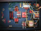
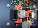
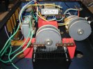
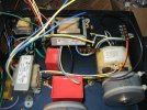
......Much more work to do. C1 and L2 are placed but not mounted. Extra Keystone #817 terminal strips have been added with decent ( high up ) access, to allow for easier Phase Alignment of AC transformer feeds......to enable a proper uniform polarity.
Imagine 1,500 Ampere ( instantaneous ) GTO capacitors, uniquely combined with two 6 Ohm Filter Chokes ....2021's favorite power supply configuration.
Thank you again - for looking, following along.
Jeff
Beginnings of the Power Supply, ...........pre wiring. Little spare room.


......Much more work to do. C1 and L2 are placed but not mounted. Extra Keystone #817 terminal strips have been added with decent ( high up ) access, to allow for easier Phase Alignment of AC transformer feeds......to enable a proper uniform polarity.
Imagine 1,500 Ampere ( instantaneous ) GTO capacitors, uniquely combined with two 6 Ohm Filter Chokes ....2021's favorite power supply configuration.
Thank you again - for looking, following along.
Jeff
Last edited:
IndianEars
Well-Known Member
Superb Pics!11-07-2021........... Mini Photo Report
Beginnings of the Power Supply, ...........pre wiring. Little spare room.
View attachment 63951View attachment 63952View attachment 63953View attachment 63954
......Much more work to do. C1 and L2 are placed but not mounted. Extra Keystone #817 terminal strips have been added with decent ( high up ) access, to allow for easier Phase Alignment of AC transformer feeds......to enable a proper uniform polarity.
Imagine 1,500 Ampere ( instantaneous ) GTO capacitors, uniquely combined with two 6 Ohm Filter Chokes ....2021's favorite power supply configuration.
Thank you again - for looking, following along.
Jeff
Thanks
11-14-2021 .................. Minor Progress Report
Slow, but positive progress, did almost everything two times, to get it modestly acceptable .....................C1 ( 30 uF WIMA DC Link ) and L2 ( 6 Ohm Hammond 159ZA ) not yet installed,...... both go in this picture's space.
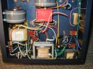
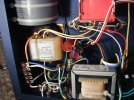
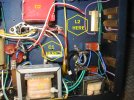
Thank you for looking. Two R-Core ( Softone RW-20 ) output transformers got mounted on the chassis' top-side this past week. Top-side looks very cool to me. Need to take photos of that.
Jeff
Slow, but positive progress, did almost everything two times, to get it modestly acceptable .....................C1 ( 30 uF WIMA DC Link ) and L2 ( 6 Ohm Hammond 159ZA ) not yet installed,...... both go in this picture's space.


Thank you for looking. Two R-Core ( Softone RW-20 ) output transformers got mounted on the chassis' top-side this past week. Top-side looks very cool to me. Need to take photos of that.
Jeff
Last edited:
Today - a partial discussion of capacitors and applying of same .
Warning :
( All that follows is in my own experience, in my own opinion, my own experience, and in my own belief system : )
A basic truth is that in audio, there is not a single capacitor that exists, that plays all ranges of the music, at their fullest fidelity. Not a one, no matter what the cost or size !!
Generally speaking a large microfarad cap plays the low end well, and vice versa for a small microfarad cap being able to intrinsically play the high end well. This relationship of cap uF and frequency has been known for decades, but sadly, very little has been done in audio, so as to OPTIMIZE a capacitor in a circuit, so that the cap plays well at ALL audio frequencies.
Only a handful of Manufacturers consistently practice combining multiple capacitors to obtain a wide playback response. Out of that handful, I am only aware of one, who seems to do it fabulously well, but I would hope this is not the sole proponent and instance.
Most ( 90% plus) of commercial audio equipment is designed to give the listener a decent swath of the midrange's music information. It is cheap and easy to do this, with a single ( musically deficient ) capacitor in a circuit's " capacitor" position. Conversely, it takes LOTS of money, and a talent in design, to develop a pre amplifier or amplifier that plays back music convincingly. Manufacturers would promptly go broke, providing such a level of playback.
What are the audio frequencies ???
Easy...same as the frequencies of live unamplified music. Music is wide band, and audio playback equipment should be, IF it is to mimic music.
Important Note: One does NOT need to have stellar hearing, to appreciate the music content in the highest frequencies. What is " beyond" our measured high frequency hearing, filters down, into the midrange, where people with compromised overall hearing, will readily appreciate the " above - 20KhZ " information, and say " thank you " for providing it in your audio equipment. Look up the word " resultants ".
AS a DIYer, one can apply whatever they want to have in their circuits, for any capacitor position !!! Assuming the DIYer can afford the parts cost, their motive is purely music enjoyment. Turning a profit on a part's cost, is not in the equation.
OK, let us " GET TO IT !!! "
The simplest answer is to combine multiple capacitors of high quality ( film types ) and of differing smaller values, into a circuit's single capacitor position. That makes sense, but you HAVE to do so - properly. This approach ASSUMES the builder has certain capabilities, which most do not have, unfortunately.
FIRST, it assumes the builder knows what precise uf ( microfarad ) value capacitor plays in each music range. Very very few audiophiles know !!!
SECOND, it assumes the builder has a audio system sensitive enough, good enough overall, to reveal where there exists playback problems.
THIRD, it assumes that the builder has the experienced hearing to quickly determine where a frequency range is missing in playback, or over-emphasized in playback. ( Where adjustments are needed. )
FOURTH, it assumes the builder knows what brands, types and values of film caps to add to a multiple bunch.
FIFTH, it assumes the builder has sufficient financial capability, to purchase the best caps for the job . This factor sadly, often looms largest, to hinder one's genuine build progress and education.
WHAT HAPPENS :
Someone " tries" multiple film bypassing, but ONLY by adding one cap. Yes, that region which the newly-added cap should play, may be better, but now, there are discontinuities, suck-outs, holes, VS hearing one cap alone !! At that point, they may "give up " or at the most, they may try two added caps. In all likely hood, possibly or probably one or both of the added caps are now the wrong uF values needed !! So, the ill prepared audiophile " gives up " on multiple film cap bypassing. Does that describe you ??? I did this, very early on.
Several decades ago, there was a favorite article of mine presented in I think USA's " Sound Practices " magazine. It covered a two stage DIY direct coupled SET amplifier build, by a couple of Italian DIYers, Marzio and Jelasi. It is on-line today . See it easily by clicking on the following URL :
What I want to bring to everyone's attention is their use of multiple film cap bypassing, of the most basic type, presented in writing, way back then. Notice in their posted parts list, out of seven cap positions in a mono amp, six cap positions are specified to be of three differing values. A main cap, and two specific value, constantly prescribed values .
Read the article.
We can do better than that circuit in 2021 BTW !! Notice the Italians' C2 through C7 are all " Triplet Bundles ". Differing uF MAIN caps as needed, each combined with a 0.22uF and a 0.022 uF film capacitor as a bypass !!!! Six out of seven cap positions, fully bypassed !!!
Hooray for the DIYers from Italy to divulge this information.
For your information, 0.22uF is probably the one best uF value to enhance the middle mid-range of music frequencies. Also, 0.022uF is likewise the best uF value in a SINGLE cap, to enhance the upper most frequencies, music's top-end.
How come it is three or maybe four decades later, where this finally gets pointed-out to interested-in-audio readers. ???
OK, BACK to 2021, this 6005 build.
1) For less chance of gaps, ( and better overall musical expression ) this thread's earlier-described" Modules " have not two or three caps in a bundle, but more like five minimum, starting with a film cap value optimizing the mid-bass.
2) Film caps available in 2021, such as WIMA caps, are lower in ESR and higher in performance, than Marzio's EARLY caps used in his filter chain. WIMAs just need some minor help, also possibly to offset wiring losses. So, for caps located in the 6005 amp's first three filtering stages ( C1, C2, C3, / 30uF, 80uF, 50uF ) we only need to address the music range where Marzio and Jelasi ( and others today ) might use a 0.022 uF cap.
3) But we wanted a bit more than what a single high frequency cap provides. In lieu of a single 0.022uF, we employ a single 0.033uF bypass AND a single 0.01uF bypass, ( to cover the highest of highs ) well enough. This combo of 0.033uF and 0.01 uF, ( assuming you select good caps ), will out-play musically a single 0.022uF cap.
We do not allow caps bodies to closely touch each other, so as to minimize field interactions. Picture's worth a 1,000 words.
C1 bypassing with an unshown 5 uF GTO :
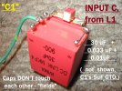
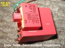
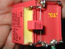
C2 with a 5 uF GTO :
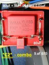
AND FINALLY :" C3, .................no GTO, GTOs just go to OUTPUT stage duty :
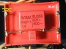
Thanks again for looking. This multiple bypassing above was done on Sunday 11-14-21.
Jeff
Warning :
( All that follows is in my own experience, in my own opinion, my own experience, and in my own belief system : )
A basic truth is that in audio, there is not a single capacitor that exists, that plays all ranges of the music, at their fullest fidelity. Not a one, no matter what the cost or size !!
Generally speaking a large microfarad cap plays the low end well, and vice versa for a small microfarad cap being able to intrinsically play the high end well. This relationship of cap uF and frequency has been known for decades, but sadly, very little has been done in audio, so as to OPTIMIZE a capacitor in a circuit, so that the cap plays well at ALL audio frequencies.
Only a handful of Manufacturers consistently practice combining multiple capacitors to obtain a wide playback response. Out of that handful, I am only aware of one, who seems to do it fabulously well, but I would hope this is not the sole proponent and instance.
Most ( 90% plus) of commercial audio equipment is designed to give the listener a decent swath of the midrange's music information. It is cheap and easy to do this, with a single ( musically deficient ) capacitor in a circuit's " capacitor" position. Conversely, it takes LOTS of money, and a talent in design, to develop a pre amplifier or amplifier that plays back music convincingly. Manufacturers would promptly go broke, providing such a level of playback.
What are the audio frequencies ???
Easy...same as the frequencies of live unamplified music. Music is wide band, and audio playback equipment should be, IF it is to mimic music.
Important Note: One does NOT need to have stellar hearing, to appreciate the music content in the highest frequencies. What is " beyond" our measured high frequency hearing, filters down, into the midrange, where people with compromised overall hearing, will readily appreciate the " above - 20KhZ " information, and say " thank you " for providing it in your audio equipment. Look up the word " resultants ".
AS a DIYer, one can apply whatever they want to have in their circuits, for any capacitor position !!! Assuming the DIYer can afford the parts cost, their motive is purely music enjoyment. Turning a profit on a part's cost, is not in the equation.
OK, let us " GET TO IT !!! "
The simplest answer is to combine multiple capacitors of high quality ( film types ) and of differing smaller values, into a circuit's single capacitor position. That makes sense, but you HAVE to do so - properly. This approach ASSUMES the builder has certain capabilities, which most do not have, unfortunately.
FIRST, it assumes the builder knows what precise uf ( microfarad ) value capacitor plays in each music range. Very very few audiophiles know !!!
SECOND, it assumes the builder has a audio system sensitive enough, good enough overall, to reveal where there exists playback problems.
THIRD, it assumes that the builder has the experienced hearing to quickly determine where a frequency range is missing in playback, or over-emphasized in playback. ( Where adjustments are needed. )
FOURTH, it assumes the builder knows what brands, types and values of film caps to add to a multiple bunch.
FIFTH, it assumes the builder has sufficient financial capability, to purchase the best caps for the job . This factor sadly, often looms largest, to hinder one's genuine build progress and education.
WHAT HAPPENS :
Someone " tries" multiple film bypassing, but ONLY by adding one cap. Yes, that region which the newly-added cap should play, may be better, but now, there are discontinuities, suck-outs, holes, VS hearing one cap alone !! At that point, they may "give up " or at the most, they may try two added caps. In all likely hood, possibly or probably one or both of the added caps are now the wrong uF values needed !! So, the ill prepared audiophile " gives up " on multiple film cap bypassing. Does that describe you ??? I did this, very early on.
Several decades ago, there was a favorite article of mine presented in I think USA's " Sound Practices " magazine. It covered a two stage DIY direct coupled SET amplifier build, by a couple of Italian DIYers, Marzio and Jelasi. It is on-line today . See it easily by clicking on the following URL :
What I want to bring to everyone's attention is their use of multiple film cap bypassing, of the most basic type, presented in writing, way back then. Notice in their posted parts list, out of seven cap positions in a mono amp, six cap positions are specified to be of three differing values. A main cap, and two specific value, constantly prescribed values .
Read the article.
We can do better than that circuit in 2021 BTW !! Notice the Italians' C2 through C7 are all " Triplet Bundles ". Differing uF MAIN caps as needed, each combined with a 0.22uF and a 0.022 uF film capacitor as a bypass !!!! Six out of seven cap positions, fully bypassed !!!
Hooray for the DIYers from Italy to divulge this information.
For your information, 0.22uF is probably the one best uF value to enhance the middle mid-range of music frequencies. Also, 0.022uF is likewise the best uF value in a SINGLE cap, to enhance the upper most frequencies, music's top-end.
How come it is three or maybe four decades later, where this finally gets pointed-out to interested-in-audio readers. ???
OK, BACK to 2021, this 6005 build.
1) For less chance of gaps, ( and better overall musical expression ) this thread's earlier-described" Modules " have not two or three caps in a bundle, but more like five minimum, starting with a film cap value optimizing the mid-bass.
2) Film caps available in 2021, such as WIMA caps, are lower in ESR and higher in performance, than Marzio's EARLY caps used in his filter chain. WIMAs just need some minor help, also possibly to offset wiring losses. So, for caps located in the 6005 amp's first three filtering stages ( C1, C2, C3, / 30uF, 80uF, 50uF ) we only need to address the music range where Marzio and Jelasi ( and others today ) might use a 0.022 uF cap.
3) But we wanted a bit more than what a single high frequency cap provides. In lieu of a single 0.022uF, we employ a single 0.033uF bypass AND a single 0.01uF bypass, ( to cover the highest of highs ) well enough. This combo of 0.033uF and 0.01 uF, ( assuming you select good caps ), will out-play musically a single 0.022uF cap.
We do not allow caps bodies to closely touch each other, so as to minimize field interactions. Picture's worth a 1,000 words.
C1 bypassing with an unshown 5 uF GTO :


C2 with a 5 uF GTO :

AND FINALLY :" C3, .................no GTO, GTOs just go to OUTPUT stage duty :

Thanks again for looking. This multiple bypassing above was done on Sunday 11-14-21.
Jeff
Last edited:
- Status
- Not open for further replies.
Wharfedale Linton Heritage Speakers in Red Mahogany finish at a Special Offer Price. BUY now before the price increase.
Similar threads
- Replies
- 0
- Views
- 791


