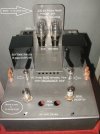
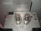
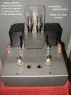
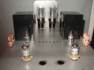
New Design, SE 6005 Directly Coupled Audio Amplifier

Status
Not open for further replies.
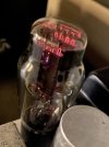
Question: Has anyone here been using these Russian rectifier tubes, with symmetrical HARP filaments, in place of a 5U4G rectifier?

HARP 1 of 3.jpg


HARP  2 of 3.jpg


HARP 3 of 3.jpg

If so, what has been your subjective performance - opinion of them ??

Thanks,

drlowmu
 
Last edited:
6-04-2021 .............................. UPDATE on new SE DC 6005 Amplifier Design.


This amplifier's circuit design is complete.

Construction of this new design has been delayed the past two months due to parts availability.

As it turned out, there were no off-the-shelf power transformers available from my usual go-to source ( Hammond ), that would give the precise conservative operating voltages. At this juncture, it looks like Shilchar Technologies might supply a 320 VA R-Core custom design to power the 95 VA load. If so, that will take them about six weeks to produce these ( half a dozen ) power transformers.

The " Harp " type 5U4G rectifier tube , subject of the post #83 right above, has been fully evaluated - and it is fully known now. These tubes will certainly get used, two in each stereo amplifier. I am highly pleased with their performance.

Lay out of the new amp's major components, to develop a solid 14 gauge ( welded corners all-steel ) chassis, was the next step.

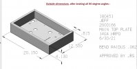
Two days ago I submitted drawings to a local steel fabrication facility. They will Cad-draw, for plasma cutting, the chassis exterior dimensions, and plasma cut all the component holes, ( tube socket, transformers, RCA jacks, Cardas speaker binding posts, On-Off switches, fuseblock, 20A. IEC inlets, handles for carrying ) . Six chassis ( one for my use, two for build-clients, and three for DIY friends ).

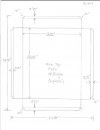
Amateur / hand-drawn specifications for Plasma Cutting the 14 gauge steel, are partially shown.


1 0f 5.JPG

3 of 5 EDITED.jpg

The 6005 tube amplifier, as designed here in this thread, is something I am most anxious to produce.

Why ?? I hear this 6005 tube itself, as being superior sonically .......to almost all other audio output tubes ( due to its symmetrical construction ). Additionally, no one has ever applied such a circuit ( shown earlier in this thread, see post #57 ) to an audio amplifier. This resulting amplifier, I actually already know, is going to be so much fun - to own and hear. The one minor downside - this project is taking much longer than I would have hoped it would.
 
Last edited:
Great to know developments. Will be eager for your listening impressions later.
 
6-17-2021 UPDATE

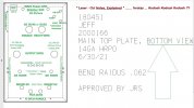
Here is what a uncorrected portion of the CAD plans, for metal working looks like, VS posted earlier hand drawings.

Stereo 6005 beam tetrode SE DC amp:

Snipped , not quite right, TOP PLATE edited.jpg

The metal work is to be precisely done at a company, local to me. See their operation !! Laser cutting is superb.

The web site URL is :
I am so happy that I do not have to hand-drill and Greenlee Chassis Punch by hand, six of these stereo chassis.

Jeff
 
6-30-2021 PROGRESS REPORT

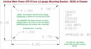
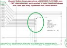
The metals fabrication company gave me these to approve today, prior to laser cutting the six new amplifier chassis. Looked OK to me. I explained it, for you all.
SNIP  Three Quarters Bottom view  edited.jpg

SNIP Bottom view edited.jpg

Shilchar R-Core 320 VA MOUNTING BRACKET edited.JPG

SNIP Bottom Cover and Vibration ISOLATION Plate edited.jpg
Thank you for looking. Six of these get fabricated, starting any day now. Midwest MetalCraft, Windsor, MO USA. Excellent folks !!

SEE them here .... https://www.4mmc.com/fabrication

Jeff
 
Last edited by a moderator:
7-24-2021 UPDATE

After several weeks, the six chassis were finished and picked up at the Metal Machine Shop. Next week, the corners of the metalwork will go out for welding and grinding smooth.

It was fun to place parts on this one chassis, just to see how it looks, and if I got the proportions reasonable looking in 3-D. What do you think ??
002 edited 2.jpg
and the rear of the chassis, below 007 edited.jpg
The Power Transformers ( R-Cores, 320 VA from Shilchar Technologies) made to my specifications, are supposedly done. They all will arrive at Hari Iyer's home, possibly next week, and he will mail them to me. Thanks to two fantastic FMs, Sadik and Hari, for their unselfish and fully trusted help.

Thanks for looking. Off to the welders , to do the corners, next.

Jeff
 
Last edited by a moderator:
Thanks for the update, Jeff.....

All 6 amps must be eagerly awaiting the R Core Transformers !
 
7-25-2021 UPDATE

After a day of simply staring at the new chassis, I came up with the idea of turning the Softone RW-20 R-CORE Output Transformers, 90 degrees, so that their shape was in the same axis as the chassis' 0.618 percent shape. Now the two XFRS are in " harmony" visually, with the rest of the top side / chassis' shape.

It REALLY "opens up", the visual view, from all angles, and I prefer seeing this, a whole lot more, than yesterday's orientation of the RW-20s.

It is simply AMAZING to me, from different distances, and different angles, different viewing elevations, how much more I like this " shape-harmonious" RW-20 / Chassis orientation. Not shown, but side view from any distance is now killer. Any angle.
012  edited.jpg
Above, the above six tubes seem to " stand out " more so on their own, all is in harmony, visually !!!!

Below : Chubby Checker.... " Lets DO the TWIST " !!
Chubby Checker.JPG
Jeff really likes this look , from all angles.

Note : 0.618 is the "Golden Ratio", also called "Phi". This is repeated in nature, in numerous ways, for many thousands of years.

I am so happy now. Thanks - for putting up with me.

Could you begin to imagine how totally cool this amp will look in evening listening, lights off, IF we end up deciding to use the 5C3S " harp" rectifier tubes, two very large rectifier tubes, side by side, viewable easily ??? More testing needs to be done, to know if this will come about. It is possible at this point in time, just not yet decided. Premature. 5C3S is shown below, the ultimate rectifier filament light show.
HARP 1 of 3.jpg
 
Last edited by a moderator:
08-31-2021 ............... Mini UPDATE

A box with eight Shilchar ( R-Core 320 VA ) custom - made Power Transformers were shipped from Thane, INDIA, to me in the USA, t.oday.

Expected arrival - in about ten days. Thanks so much......F.M.s Hari Iyer and Sadik.

Chassis are in the shop in my town, getting corners welded ( 14 gauge steel ). More to follow.

Heatsinking the Cathode Resistors of a Direct Coupled Amplifier :

In a two stage directly coupled amplifier, the entire Output ( or Finals ) stage must be " raised" above the amp's ground voltage, by a) the amount of voltage on the plate of the Input tube and b) by the self-bias voltage required for the Output / Finals tube to operate.

In a way, the entire direct coupled amp's operation " rests " upon a carefully-implemented Cathode resistor ( Rk ) of the tube in the second stage.

This new 6005 amp has 210 VDC on the plate of the first ( Driver ) tube, and the 6005 tube requires 15 volts to be properly biased. So, with simple addition, the Cathode resistor needs to put the 6005's cathode voltage 225 VDC above ground.

This always requires a large and powerful resistor, in any DC amplifier, for the Output tube's cathode resistor.

At 32.2 mA. of bias, each 6005 will have an Rk that power-dissipates ( 225 VDC times 0.03233 Amperes ) constantly 7.27 Watts per cathode resistor, one Rk for each channel.

All resistors " sound different " from each other. It is even more difficult to choose resistors based on their sound quality - when we need to constantly dissipate 7 plus Watts in one !! From experience, for high-powered resistors, thankfully I know there are three acceptable resistor brand / type choices., resistors that sound good !! First is a vintage wirewound Ohmite Brown Devil, 200 series. Second is a more modern ARCOL HS series, 50 Watt wirewound / chassis mount. Third is a very modern Caddock special " Power Tab" film resistor. These three will be acceptable, music performance-wise.

I decided to employ the Caddock Power or Kool Tab film resistors. Here is the Michael Percy catalog data :
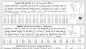
Caddocks from Percy.jpg
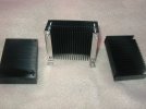
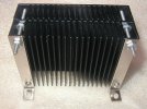
The Caddock Film resistors are designed to be mounted directly onto the metal chassis, or any large heatsink, to dissipate their 20 Watts or so of rated power. There is a large ( 2.375 by 3.5 by 0.75 inch ) black annodized aluminum heatsink I like to employ. It has 21 fins, so it has lots of surface area, to dissipate power and cool the " Kool - tab " device.

In this 6005 amp's thread, shown on Pages 1 , first post, second photo - we can clearly see one of these heatsinks, cooling off both channels' Cathode Resistors ( Rk ) in the prototype stereo amp. ( see photo ). I was never happy with this. I thought the heatsink was not adequate, to keep the resistors' really as cool as I would like, for long term reliability...thinking 100 years !! So, for the finished build, I decided last month to enlarge the heatsink's cooling capability, while at the same time, conserving internal chassis space. I wanted the execution to be simple, and mount with two bolts. Here is what I came up with :
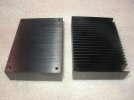
008 (3).JPG001 (4).JPG004 (3).JPG
.The Kool Tabs get mounted on the flat surface.

This uses 4-40 USA stainless steel hardware. Four two inch long bolts, a dozen 4-40 nuts, and two Keystone Electronics 1568 " board brackets ". All readily-available parts. I am quite pleased with the simple assembly, and wanted to show it to you !! The six new chassis, already have adequate holes for ventilation - laser cut on the top and bottom.
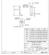
1567-71 SNIP  KEYSTONE.JPG
Since the entire DC amp " rests" on the two Cathode ( Rk ) resistors, I thought it would be good to double the heatsink size as shown. This new doubled-up heatsink dissipates 7.27 Watts times two channels for stereo, or about 14 plus Watts, continuous.

I hope, " for 100 years ".

Jeff
 
Last edited by a moderator:
I just yesterday received this writing on audio design, and the problems associated with different parts and topologies. Excuse his very casual language and writing style, but J.C. has lots of audio design experience, and he is pretty much correct. He only, however brings up the problems.

This thread, on a 6005 amp, is my 2021 solution to his posed trade-offs in design. It is just my simple well-engineered two-stage directly coupled SE amplifier .

Not all readers will follow along and appreciate J.C's written insights, but those who can, should certainly enjoy his writing. I did.

- - - - - - - - - - - - - - - - - - - - - - - - - - - - - -

“direct coupled DC amplifiers are the least subtractive and, when done right, the least additive of all possible circuit approaches. by that i mean they lose things and add extra stuff you don’t want, the least. that is my opinion. it is based on 30 years of building all kinds of crap for many manufacturers and clients and for my own curiosity. what you want, or at least i do, is nothing but wire and tubes from input to output. i’ll accept a resistor or two, for stability or function, but it is an ideal to get rid of them too. sometimes you can’t and it’s better to have them than not…

anyway, no caps, no transformers… nada. but how is that possible? well, it is and it isn’t. yes, you can make an all dc otl line and power amp, and servo and safety the output… i have done a few simple ones. but i have ended up accepting the output trans in a power amp, at least for the time being. the isolation it provides is a bigger advantage than the disadvantage of the back emf of a speaker straight into the output impedance of an otl amp. don’t get me wrong. transformers kill off some of the fine detail and the low bass. they do. but the tricks you do to get the output impedance down low enough on an otl stage adds worse crap than what you end up losing with the trans… no free lunch. and caps? well, you still sometimes need them to isolate the power supply of one stage that shares power with another. i’d prefer not to, but how many power supplies do you want to build? caps in the supply seem to be necessary, but how necessary is a good question to ask all the time.

what’s wrong with caps? what’s wrong with transformers? nothing! the universe was incredibly generous to us when it wove together electricity and magnetism. but, in practice, and this is analog 101, the material science of these things is complex. caps are not simply caps, but a blend of resistors, inductors, other capacitors, a tiny rechargeable battery, a really tiny heater, a point contact diode, and a time machine. that goes quadruple for a transformer. many DIYers think that because there are only four wires, a single ended output transformer is “simple”. hahahhahahaahahahahahahahahahahaha! in your dreams, suckah! it’s interesting to look at the “simplified” equivalent circuit for a single ended transformer… “how did all those extra parts get in there?” this doesn’t include the lossy stuff or the parasitics. there is more L, some C and some weird spongy stuff you don’t want to know about. simple right? simple to solder in you mean… a transformer is NOT a simple device and adds a lot of electrical complexity. if you have a problem with this you don’t want to see the better more accurate model one uses to finesse. 4 wires my ass!

film capacitors have less issues than transformers, for sure, but there is still no free lunch. they store energy and then release it… but hang on to a little of it, then filter some of the surplus into whatever happens after a time, but not all… store some more the next trip, etc. and god forbid you block the thing in hard clipping into a fixed biased output stage. yowza! clipping performance is a big problem for cap coupling and represents a boundary. a boundary that transformers and dc coupling don’t share. caps have inductance too, a very small amount, but enough to radiate if the swing is big enough (which it is in a driver stage for a power triode). radiated emf is a pain in the ass wherever it is. even if it’s intentional. but especially when it radiates into the high impedance points of a circuit, especially if it creates a feedback path doing so. still, caps at those large AC voltages are pretty benign. especially in simple tube circuits. the place they really suck is at small signal levels. the reason is that the lossy stuff, the hysteresis, the leakage and the dielectric absorption are relatively fixed in magnitude… small. but if your signal is small they can be of close enough magnitude to be a problem. there is also some voltage variable character but it’s really small… unless the signal is small and the gain is large. preamps. ugh. i have given up on coupling caps in preamps. even teflon and polystyrene have a dull lossy sound that goes away as soon as they do. those are the GOOD caps! i used to rely on that to tone shit down. but at the end, they introduce more trouble than they solve. transformers actually do better at small signals. but they have many many issues, and some of the same issues as caps only in reverse.

transformers crap out at big swings of current or voltage. they add 3rd harmonic and ringing if they combine badly with other inductors… other basic problems are loss of fine detail, stray field pickup (they are antennas too), bandwidth limiting, and multiple pole filtering and varying phase shift. but most of all, one trans represents minimally a bandpass filter… if the poles of this coincide with other poles in the system, instability, ringing, distortion and delay are all added. this means you have to watch your poles with trannies… (you know who you are girls).

nope. best is to have none of that. but barring that (which is nearly always), best is to have the least possible of that.”

J.C. Morrison
 
Last edited:
I just yesterday received this writing on audio design, and the problems associated with different parts and topologies. Excuse his very casual language and writing style, but J.C. has lots of audio design experience, and he is pretty much correct. He only, however brings up the problems.

This thread, on a 6005 amp, is my 2021 solution to his posed trade-offs in design. It is just my simple well-engineered two-stage directly coupled SE amplifier .

Not all readers will follow along and appreciate J.C's written insights, but those who can, should certainly enjoy his writing. I did.

- - - - - - - - - - - - - - - - - - - - - - - - - - - - - -


film capacitors have less issues than transformers, for sure, but there is still no free lunch. they store energy and then release it… but hang on to a little of it, then filter some of the surplus into whatever happens after a time, but not all… store some more the next trip, etc. and god forbid you block the thing in hard clipping into a fixed biased output stage. yowza! clipping performance is a big problem for cap coupling and represents a boundary. a boundary that transformers and dc coupling don’t share. caps have inductance too, a very small amount, but enough to radiate if the swing is big enough (which it is in a driver stage for a power triode). radiated emf is a pain in the ass wherever it is. even if it’s intentional. but especially when it radiates into the high impedance points of a circuit, especially if it creates a feedback path doing so. still, caps at those large AC voltages are pretty benign. especially in simple tube circuits. the place they really suck is at small signal levels. the reason is that the lossy stuff, the hysteresis, the leakage and the dielectric absorption are relatively fixed in magnitude… small. but if your signal is small they can be of close enough magnitude to be a problem. there is also some voltage variable character but it’s really small… unless the signal is small and the gain is large. preamps. ugh. i have given up on coupling caps in preamps. even teflon and polystyrene have a dull lossy sound that goes away as soon as they do. those are the GOOD caps! i used to rely on that to tone shit down. but at the end, they introduce more trouble than they solve. transformers actually do better at small signals. but they have many many issues, and some of the same issues as caps only in reverse.


nope. best is to have none of that. but barring that (which is nearly always), best is to have the least possible of that.”

J.C. Morrison
AWESOME Post.

I love his style and more importantly the content. Clearly he has a lot of practical AND theoretical knowledge....

I would love to learn more about "clipping performance is a big problem for cap coupling" Would appreciate any pointers.

Sincere Thanks for a Rare and insightful post. :)

Glad you enjoyed it. I was actually thinking of you, when I decided to post it. Glad you read it.


J.C is also a trapeze artist., from New York City originally. I "baptized" him, and a co-DIY friend at the time , into low DCR. -1980s His buddy ( now a reviewer - Herb Reichert ) wrote an article in Sound Practices magazine, on his " Flesh and Blood " DIY 300B SE amp. Herb used a 24 ohm DCR 3 HY ESPEY $ 8.00 USD surplus choke. I told him to buy it, from a surplus USA outfit called " Fair Radio ".

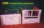
I was told all about low DCR, and the need for chokes " to be 20 Ohms DCR or less-if I can find them ", by my first audio Mentor, Mr. Robert W. Fulton , of Fulton Musical Industries. This advice occurred while designing my first from-scratch tube amp, 1981-1982. ( Push Pull Parallel 6B4G DHTs and 6SN7GTB front-end tubes, ..........one channel pictured below. ) ESPEY chokes, at 24 Ohms, was all I could find then. Now, in 2021, we have Hammond 159ZAs, which are only 6 Ohms ( takes two in series, L1/C1/L2/C2 ) and these require a 75 hour break in.

Imagine the ease and speed when delivering energy to the Finals stage, with only about 12 Ohms resistance in the path, due to the filter chokes in the amp .

Well, the pointer, if you follow J.C. Morrison, is not to use coupling caps in series with the audio signal, but instead, direct couple between two tubes.

After hearing the Serious Stereo 2A3 amps at many RMAF audio shows, that is the only thing I have built in DIY amps, for the last 15 year. Only two stages, direct coupled, single ended. I consider that specific topology the simplest and best available to us.

One Channel Only, 200+ pounds..JPG

Jeff
 
Any schematic to share on 6B4G direct coupled parallel push pull amp ? Happens to be one of my favorite tubes and much more affordable over 2A3 and 300B.

As a stop gap and to satisfy my curiosity, will attempt a simple SE 6B4G with the vintage Tamura OPT I just acquired.
Yogibear,

" Ask and ye shall receive ". Send me a P.M. with your email address, and I will gladly privately help you with a SE two stage DC amp for the 6B4G. I did not read your post carefully, and what follows below is a P-P amp. Yours would be very similar VDC -wise and tube wise, and a bit simpler !!

( The main compromise with a 6B4G is you have to use DC on the 6.3 Volt filaments, which is always a bit less good sounding than AC operation of a 2.5 Volt 2A3 tube. A minor degrade and a cost - trade-off. The second trade off is being forced to use a biplate construction, whereas modern 2A3s use monoplates, which sound superior to biplates. )
- - - - - - - - - - - - - -- - - - - - -
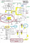
I actually have a fine " master " schematic, what I would do for myself, IF I had to do P-P.

I would strongly advise against trying to duplicate what you see in that 1980's picture in that above post of mine. Far too complex and far too costly. Its not necessary.

Power-wise, can you get away with just two 6B4Gs in Push Pull, to drive your speaker in your room? If so, in 2021, we need to do the simplest 6B4G amp circuit possible. Do you know what that is??

Two stages and directly coupled !! A single 12BZ7 into two 6B4Gs will be ideal, gain-wise and jump-factor wise !!

This simple DC amp below will probably exceed anything you likely have ever heard in P-P :

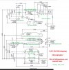
Master Schematic 4 SNIP 9-9-21 edited.jpg
I am "game" to design this for you, IF it is powerful enough to do you speakers and room. What efficiency speakers do you run?? Shilchar will make a DANDY power XFR for you, similar in " grunt and stability " to Hari's, but with slightly less VAC - to get 500-505 on the plates of the 6B4Gs.

We need for each channel a 700 Ohm choke, with as high a HYs as we can find, good for 5 mA. or more. All I could easily source was the Hammond 9 HY one shown, higher HY will be better. Have two custom made ?? The 700 Ohms DCR biases the 12BZ7's two sections, at 1.1 mA. each, to 1.54 VDC. We seek 1.5 to 1.65 VDC self bias. The choke acts like a 700 Ohm resistor, but it is also acting like a benign constant Current source, without the negative sonics of sand !! No solid state devices allowed !!

I love this topology for P-P. KISS rules.

Jeff
 
Last edited by a moderator:
Jeff, Currently confined to a small room, my current speakers are L shaped single driver OB, 8" to 12", 95dB to 100dB, measured good from 70Hz to 16-17K for the most capable ones.

I have been curious about DC and IT coupled amps, latter coz of very minimal passive components count. DC because the idea of a capacitor shaping the sonics over the tube itself is unsettling for me and defeats the actual purpose of tube amps but its a necessary evil for maximum topologies.

Mine first ever was SE Pure Class A, no NFB 6BM8 SE with option to DC but sold it to a friend before I could try the DC option. Just finished the classic Mullard EL84 PP running in Triode mode.

Been always curious on 6B4G PP and one particular build based on IT coupled. For the IT build, acquired a couple of pairs of Sansui 1000A OPTs but the Lundahls are still fleeting....

Met a person from UK who has a very peculiar cascade DC designs for tube amps but recent health issues have been weighing him down.

Sent you a PM but not sure if I have all the parts needed.

My immediate next is a very simple tube rectified F2a SE amp, for which I have all the parts.

But would certainly like to build the DC 6B4G PP some day soon. The Russian tubes are on my mind though currently there seems to be a plethora of some fine American NOS tubes selling at great prices....

Sam.


I could not find the schematic of what you are building. Can you easily PM it to me?? I see Shindo's F2a amp uses a 6AW8A input tube.

A 6AW8A seems to be a triode and pentode in one tube. If this is what the F2A amp uses as the front-end tube, to get 10 Watts, ........you are starting a build at a distinct topology disadvantage. It is too complex !!

1) It is a three stage amp. ( the extra middle stage .......loses information ).

2) It has to split the signal's phase ( and later re-combine it ).

3) It does not use all triode tubes.

I just PMed you a simple design where 1/2 a 12AX7 is DCed to the grid of a single 6B4G ( a SE amp ).

So now, we have a KISS topology. Two stage, DC coupled, SE, and all triode tubes.

In my experience, nothing can touch this, IF ( a very big word ) it is done well. ( Sadly, it is usually never done well, highly compromised ). In all cases, I am assuming the very best build, in each topology.

The SE 2A3 type amp is only 2.5 Watts. If you want to hear the best sounding amps, it is only done with proper high efficiency speakers !!

An (above) post's two stage DC P-P amp, ( 12BZ7-6B4Gs ) should easily outperform any three stage P-P amp in existence. Easily,........IF done well. Because it is two stages, and Directly Coupled.

But a two stage DC SE amp will outperform any and all P-P amps, on efficient speakers. There...... you have it.

I should say, this is all " IME" and "IMHO". Were you able to follow my logic Sam?? Less is more, when done properly. Best wishes to all.

Jeff

PS: As for " DC VS Interstage Coupled ", DC wins, hands down. Re read J.C. Morrison, a bit earlier in this thread. He agrees.
 
Last edited:
Yogibear writes :


My lowest is 1.5 wpc SE Tube 45. Drives my speakers to pretty high loudness under half of the volume. SE 6BM8 was just 2 wpc.

Tube mania has no limits...... Want to indulge in affordable tubes which don't cost more than the amp itself !

- - - - - - - - - - - - - - - - - - - - - - - - - -- - - - - - - --

Yogibear :

Tube enthusiast friends of mine will invariably call me, and ask me to design for them a two stage DC SE Type 45 amp. ( As though the Type 45 is the best output tube in audio .) I always dissuade them .

I explain, how in 2015-2017, I wasted TWO YEARS of my audio life, designing and building two DC DIY 45 amps.

My DIY designs ridiculously outperformed a friend's Yamomoto A-08 45 amp, embarassingly so - to the Yamomoto. But my DIY 45 SE DC amps' could not play full-range linearly, no matter how good was my circuit. The fault was never remotely in the circuit, but it was because of a design flaw in any Globe or ST Type 45 tube itself !!!!!!!! It simply flunks - playing the bottom end of a grand piano properly, the lower registers.

So Yogibear, this entire 6005 thread is my 2021 answer, to the shortcomings I easily heard, and do not accept at all, in the often-hyped Type 45 tube !!

To replace the ST 45, a ten dollar NOS 1950's 6005 TETRODE, ( which does play linearly, and has several other endearing qualities ) is used. 99 % of the audio world today that I survey, is unaware - has never heard - of what the 6005 tube can do, when optimized. It is superior in it's more modern tube design and construction than any vintage ST Type 45. It plays linearly !! The 45 can not. This will be much FUN - to build, to own, and to hear. Lead, and not follow.

Triodes like a 6B4G, and many 2A3s, can play a grand piano properly also.

Can you P.M. to me a schematic with some VDCs of the Klangfilm KL 204 clone?? Thanks !

Jeff
 
Last edited:
Yogibear :

Thanks very much for showing us the Klangfilm schematic. Interesting. 'Appreciated.

You probably know "exactly" how I would critique it :


" It is too complex, has too many un-needed parts in series with the signal path, which lose information."

Which parts to eliminate ?? That is easy :

a) The series " grid stoppers "
b) the two series coupling caps
c) the middle stage.

Jeff
 
Last edited:
Status
Not open for further replies.
For excellent sound that won't break the bank, the 5 Star Award Winning Wharfedale Diamond 12.1 Bookshelf Speakers is the one to consider!
Back
Top