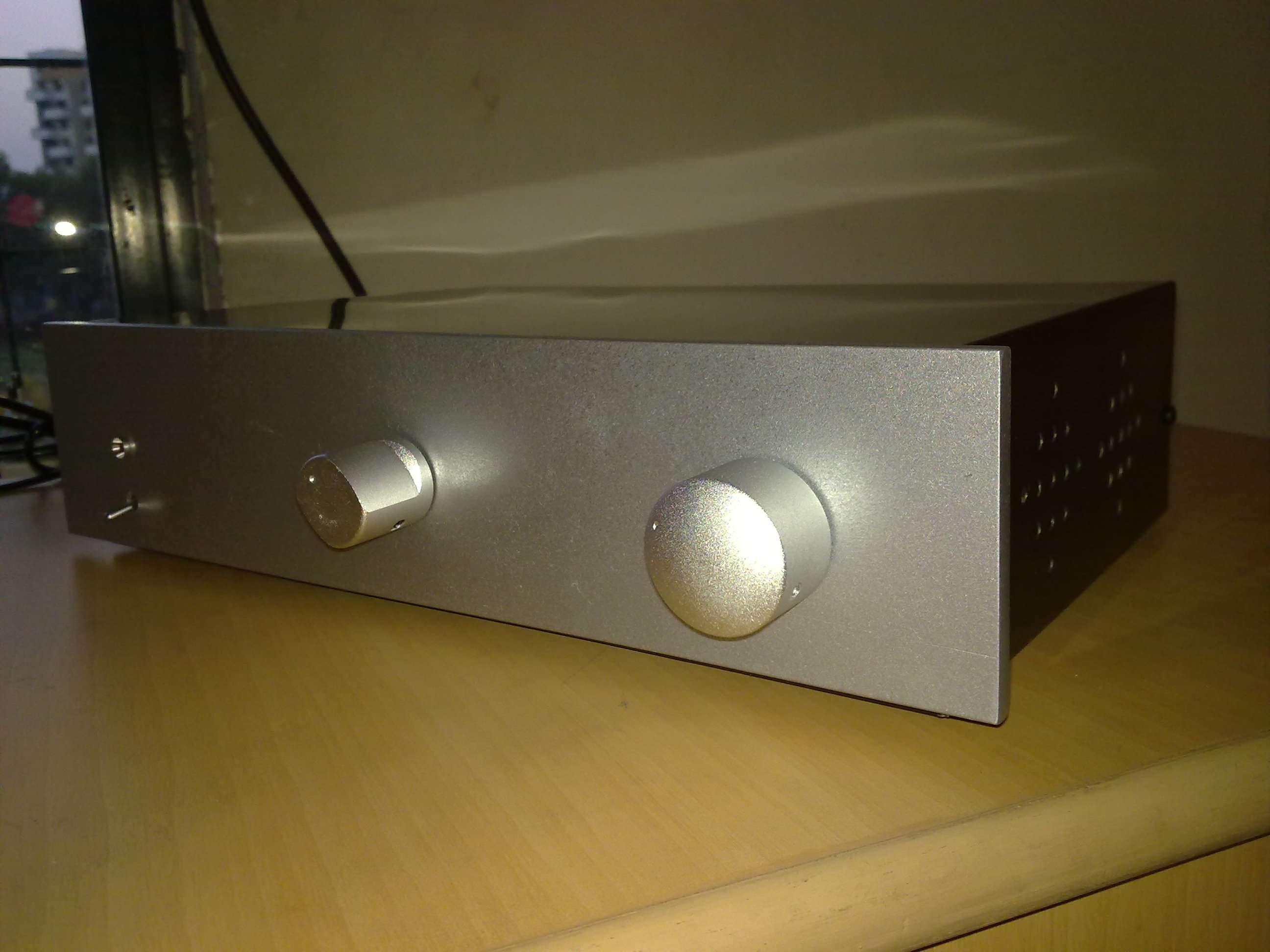
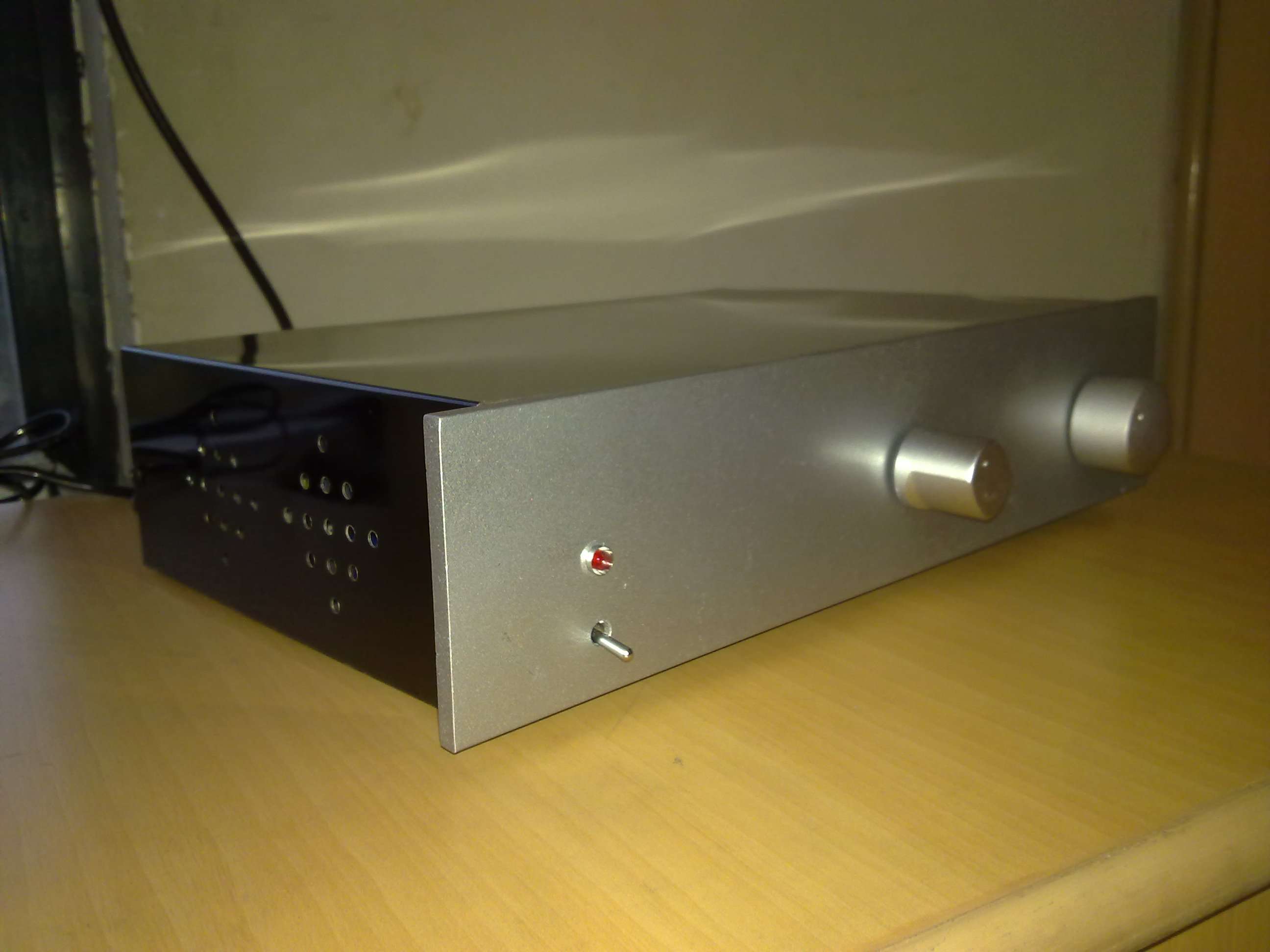
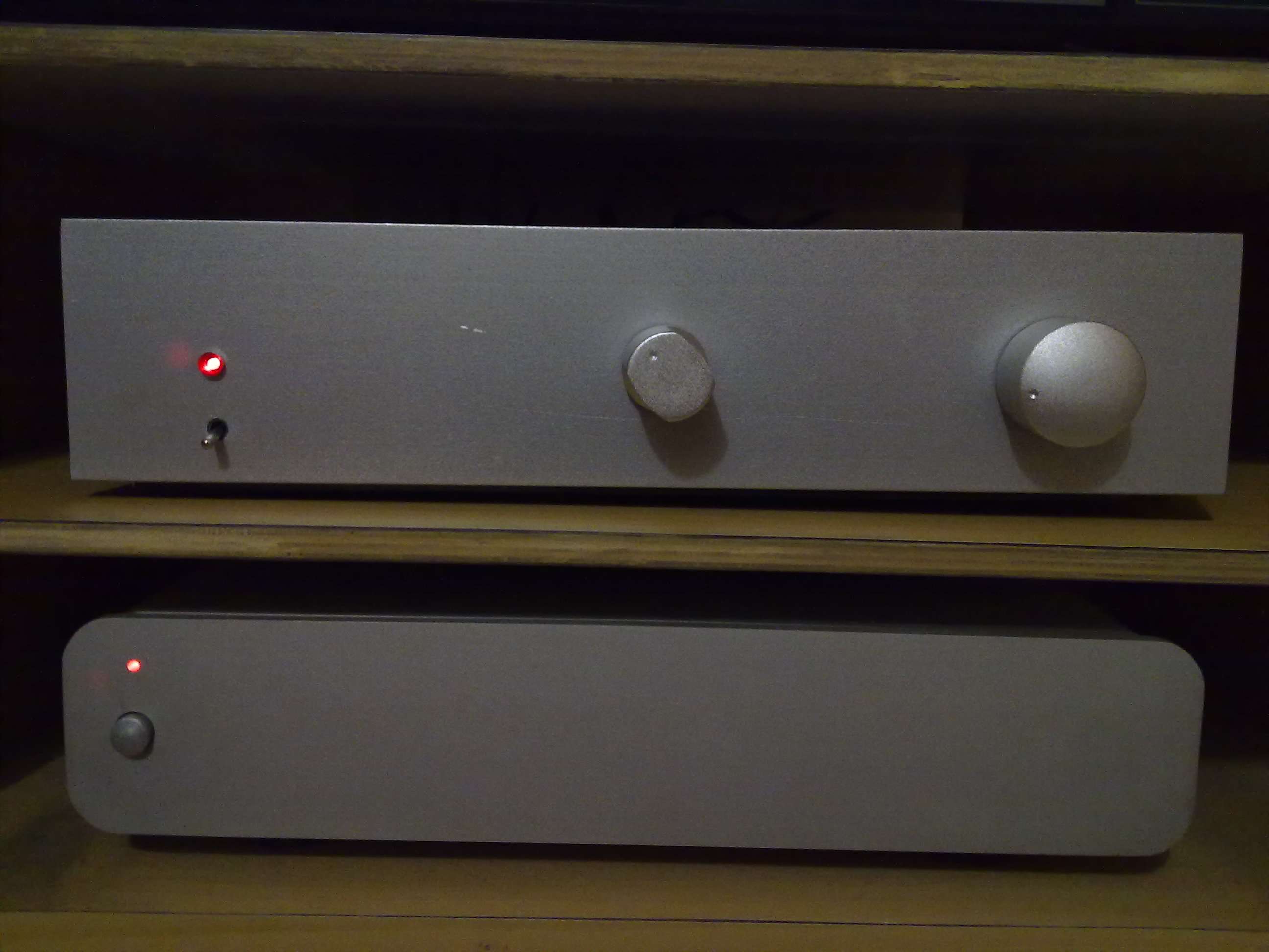
now i dont know what kind of hardware you guys are gonna use for the input selector toggle
but if its just a switch - then keeping the centre volume knob where it is and taking centre dist between the knob and the I/p selector at -50-60mm should look fine
dia 32/2 = 15
15+15 fingers)+10 ( breather)+ 10 ( considering dia of switch is 20 )+ 4 = 54 mm
you guys need to check this proportion though
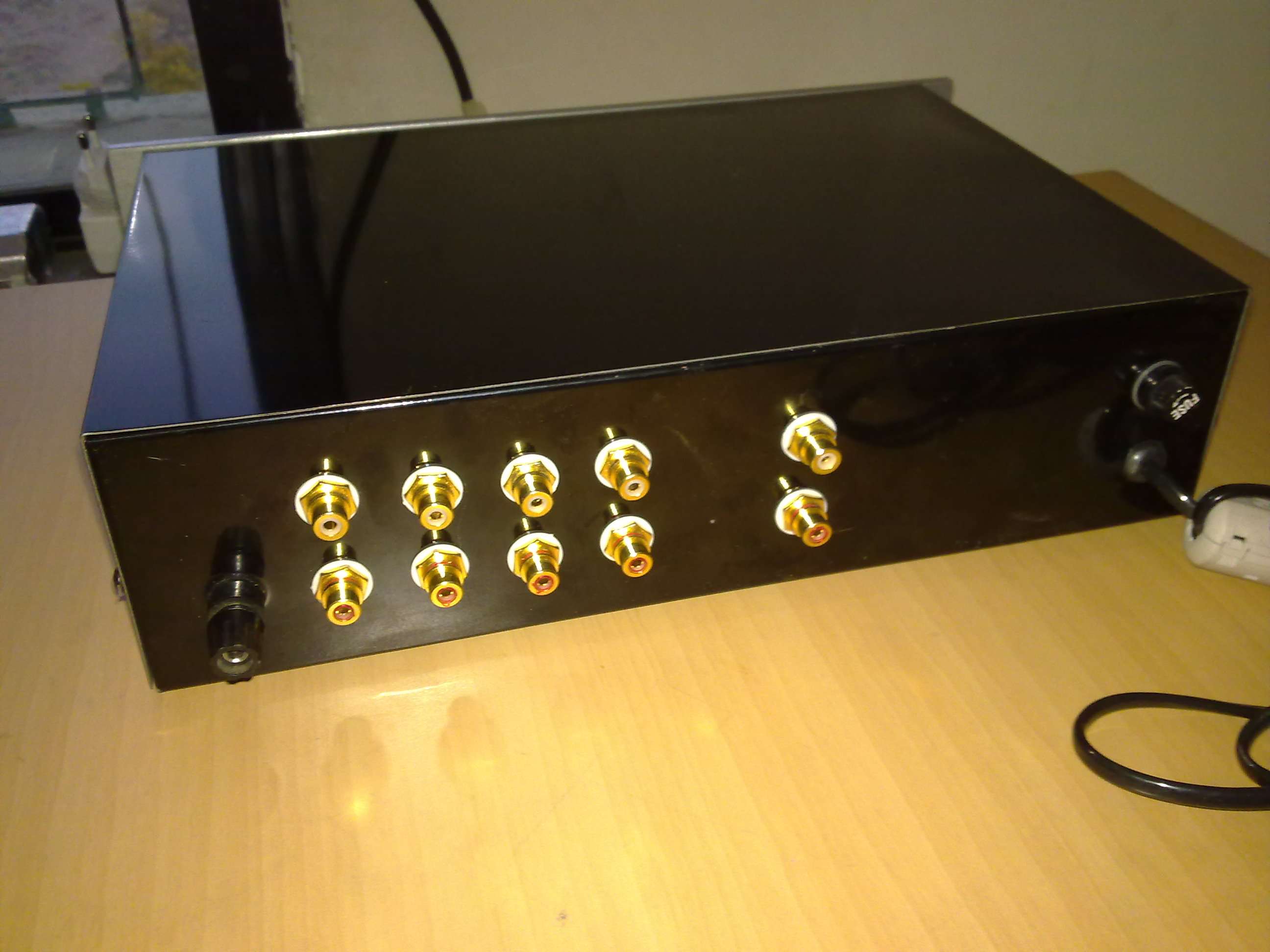
ok i have selected oms BACK plate design -- back1 - 1 pdf
the only change i propose is the follwoing
in the back1-1 pdf ( the one with 4 inputs and 1 out)
im assuming the first two holes are for the OUTPUT
these are fine
what i propose is shift the IP holes by 25mm more
Basicallly this means that the fisrt set of ip holes be kept 50mm away from the OP and not 25
the rest of the IP holes are at 25mm gap spacing
in effect the last set of IP holes are at x=200mm
the reason for doing the above is that the IP section will look differnt from the OP section
right now it just looks like a set of 10 holes equidistant to one another
Above changes have been assumed by me and scale dwg is ready
Once this is okayed i will give to make jig
I await everyones OK


