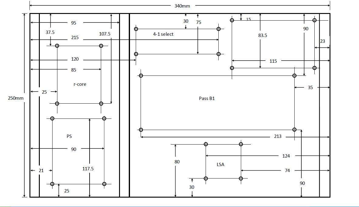
Pass B1

initial observations

isint a 5mm LED hole too large - normally clients ask for 3mm - all you got to do is stick the LED behind the hole
3mm is enough for the light to shine thru

what one of my ingenious clients does is rest the faceplate on polythene
and then inject the hole with feviquick
this forms a transparent cover on the hole on solidifying
he then sticks the led behind the faceplate

Also the backplate option 2
you can shift the IN-1 holes BELOW the In-2 holes

in this way the out looks diff from the IN
plus the IN moves away from the PSU


Please note : i know nothing about electronic ckts - so the above may be dum advice

P.S - Om sir - hats off to you
those diagrams take a crap load of work!

i need to convert them to scale now - will have to say good morning to my dtp fellow
 
Last edited:
P.S - Om sir - hats off to you
those diagrams take a crap load of work!

i need to convert them to scale now - will have to say good morning to my dtp fellow
Thanks!

initial observations

isint a 5mm LED hole too large - normally clients ask for 3mm - all you got to do is stick the LED behind the hole
3mm is enough for the light to shine thru

what one of my ingenious clients does is rest the faceplate on polythene
and then inject the hole with feviquick
this forms a transparent cover on the hole on solidifying
he then sticks the led behind the faceplate
I appreciate that. You can reduce it to 3mm. Many places, I too done same way in some projects. Here I prefer to use LED installation (panel mounting bezel). It may be difficult to procure. But I get it locally. Still your method is simple and good looking.
Also the backplate option 2
you can shift the IN-1 holes BELOW the In-2 holes

in this way the out looks diff from the IN
plus the IN moves away from the PSU


Please note : i know nothing about electronic ckts - so the above may be dum advice
That could also be done. Here PASS B1 input and output holes on PCB are matched to the rear faceplate. If you move IN1 holes then some wires will bend, Not a big deal. Do you feel that PS will have any effect on IN1? IMO that 15mm partition is there to save us. Also ours is no gain buffer. So feel free in that way for amplifying noise.
 
Last edited:
Though I did not mark holes for that it could be added next to 4-1 select board at right side space. I will make few modification into measurements.

om
how difficicult is it for you to give me a scale dwg?

im real bad at autocad
im gonna take ages
 
om
how difficicult is it for you to give me a scale dwg?

im real bad at autocad
im gonna take ages

I don't have that software handy. I will try it in paint if possible.

Other thing is I can draw on paper and send by courier on Monday.:p

BTW: I modified bottom plate in previous post.
 
Last edited:
someone said theres a software called open office
i downloaded it but cant fugure out the "office drawer"

dont even think of suggesting corel or autocad
im just too slow on them
 
Magma,
A DXF or SVG format will do?

as long as i can open it in a PC and take a printout it will be fine

basically i need scale printouts of the plates
these scale printouts are then pasted on a scrap AL piece- loaded on a CNC and drilled in one setting

this scrap aluminium piece now becomes a rough jig to drill holes in all cabs
 
as long as i can open it in a PC and take a printout it will be fine

basically i need scale printouts of the plates
these scale printouts are then pasted on a scrap AL piece- loaded on a CNC and drilled in one setting

this scrap aluminium piece now becomes a rough jig to drill holes in all cabs

OK fine. I'm not an expert here but being fiddled with a Front Panel designer software in the past from front panel express I used it to replicate what omishra provided. The purpose of that software is design a panel and send it across to them to have the panel machined for your one off requirements.
There is an option to export the file as .DXF format which I think you can use it to import into AutoCad or download that software from the link I provided and open the files (.fpd) in it and take a print out if you have an A3 printer.

The below are the screenshot just to get an idea how they look to scale.

Rear Panel: The measurements for IEC were taken for BULGIN - BZH01/Z0000/02 just to get an idea but can be adjusted for other sockets.
RearPanel_2.jpg


Front Panel
FrontPanel_2.jpg


If you need any changes like adding corner radius or the mounting holes I can add it. If the one I provided works for you I can work on the bottom panel too.
 

Attachments

Great going Ravi:thumbsup:


I have a point to ponder. Rather than spacing them apart at equidistant gaps, should we not bunch up the controls at one corner and leave the front plate for the uncluttered look?

Just a passing thought; Bouquets and brickbats are welcome.:cool:
 
Great going Ravi:thumbsup:


I have a point to ponder. Rather than spacing them apart at equidistant gaps, should we not bunch up the controls at one corner and leave the front plate for the uncluttered look?

Just a passing thought; Bouquets and brickbats are welcome.:cool:

Thanks Rajesh. It can be done. Rearranging it is a matter of minutes once I get green signal from magma that my suggestion would work for him.
 
Hi Ravi,
I think it should work fine for Magma.I would prefer only 6 RCA holes on back plate as I am not going to use more than 2 input at a time.

Regards,
Sachin
 
The below are the screenshot just to get an idea how they look to scale.

Rear Panel: The measurements for IEC were taken for BULGIN - BZH01/Z0000/02 just to get an idea but can be adjusted for other sockets.
RearPanel_2.jpg
Imp: For Back2-option - Here Left side distance should be 75mm in place of 50mm .That taken considering PCB. (opposite to my construction layout)
For option 1 displayed above please make some separation at rightmost RCA (towards IEC socket) away from remaining inputs by 50mm. (same as my construction)
IEC Socket Center should be 52.5mm from RHS and 35mm from TOP.
 
Last edited:
hum tho worker hai
Jo saheb log bolega - woh karega

though, i have finished the scale dwg of the base plate according to omishra post no.525 (modified 6.00pm pdf)

NO changes in that please

taiwanese FUSED IEC socket with light indicater switch is about 25mm in width and 50mm tall

volume control knob is about 32mm in dia
take 15mm after that for fingers

now i dont know what kind of hardware you guys are gonna use for the input selector toggle
but if its just a switch - then keeping the centre volume knob where it is and taking centre dist between the knob and the I/p selector at -50-60mm should look fine

dia 32/2 = 15
15+15 fingers)+10 ( breather)+ 10 ( considering dia of switch is 20 ) = 50mm

you guys need to check this proportion though
 
Last edited:
was just reviewing the baseplate

man
everything is a real tight fit with only 7mm between boards and sometimes just 5

had i given the baseplate dimns even 1/2 inch smaller things would have not fit

hats of to the architect- OM
you have made best use of floor plan

this might just turn out to look like some OEM base plate once the pcbs are populated!

Thanks Magma, now with S/W Architect and H/W architect too. :D

You are correct, still I am skeptical about 4-1 select and CNC boards. I have latest with me is reflected there. I expect few mm difference into that.For r-core I trusted to Sachin's measurement skills.
 
ok i have selected oms BACK plate design -- back1 - 1 pdf
the only change i propose is the follwoing - om please check and see if it makes sense and is viable


in the back1-1 pdf ( the one with 4 inputs and 1 out)
im assuming the first two holes are for the OUTPUT
these are fine

what i propose is shift the IP holes by 25mm more
Basicallly this means that the fisrt set of ip holes be kept 50mm away from the OP and not 25
the rest of the IP holes are at 25mm gap spacing

the reason for doing the above is that the IP section will look differnt from the OP section
right now it just looks like a set of 10 holes equidistant to one another
 
Join WhatsApp group to get HiFiMART.com Offers & Deals delivered to your smartphone!
Back
Top