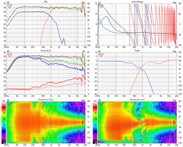
A 3-way active crossover design study

It will be easier to dig-out the noise/hiss and other issues when you get from the 88dB to the 98dB woofer and re-level everything.

If I might suggest anything, it's to not completely ignore how the driver sounds in the foam and w/o lining/damping/filling. Over time, those experiences will add-up to help you recognize patterns. You have so much going-on that acoustics hasn't yet entered the discussion, which is fine. There is recklessness available to you when in foam that will no longer be available, too. Turn the whole thing 90 deg (change CTC), add "wings" or bevels, add "foam bracing" etc as time/inclination permits. Fill the whole thing with polyester pillow stuffing. Whatever you choose, all of it will add-up in your head to patterns/learning over time :) Cardboard/foam/cheap proto cabs are a license for experimentation.
Thanks a lot for these suggestions.. I will try them out.
The hiss itself is audible only if I put my head inside the horn mouth even at higher volumes that I can use at home.. So it is not an issue as of now. But as you said, the 99dB sensitive woofer will probably get it more down. I will also try to use an L-pad if required.
From the box construction point of view, the foam box is already completely filled with polyfill.
The XPS foam material used is 1inch thick.
It is braced on the inside with same foam material using two window braces and a dowel brace.
Changing CTC experiment is one that I will definitely try as it is easy.. :)

I am also thinking about trying out the analog notch filters technique in below article for the Satori driver (in whatever configuration it ends up.. this 2 way or the original 3 way it was intended for) :) at least the notch filter part. Rest all DSP crossover.
https://purifi-audio.com/tech/ (Low Distortion Filter for PTT6.5X04-NAA)
In addition to getting the notch, there seems to be a free benefit of significantly reducing the breakup resonance-amplified distortion products, which show up as subharmonic peaks in the distortion spectrum.

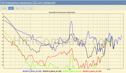
I had tried to play the WO24P without filtering. It is almost un-listenable when played full range, unfiltered. Sort of echoey, screechy sound. Makes one want to cover ears.. Notching the breakup peak, even actively, makes a lot of difference to the sound. Now I am thinking, I see rise in harmonic distortion and resonances in the impedance and HD plots of the driver here:
https://hificompass.com/en/speakers/measurements/satori/satori-wo24p-8
Would this kind of passive notch make a difference with the woofer and the CD (which also has a big breakup peak around 15.5kHz)?

Anyway, a bit more impressions before I take off for a week. :)
The prototype single speaker system has been sounding so good to my ears that I have started wondering about what I am trying to achieve technically and audibility wise with these two parallelly running projects (2 way horn, with Rosso65CDN-T, and the initial 3 way project).. Need to figure this out and continue evolving the concepts as much as possible.
The compression driver has been sounding so good that I would recommend it to anyone on the lookout for 1.4inch CDs.
Again and again, I am hearing new things in songs without even paying much attention to the system. I used to keenly listen for new things in past small (6inch woofer+ 1inch tweeter) speaker projects. But not anymore.. :)
I had all sorts of apprehensions initially thinking about the titanium diaphragm on the CD, the very narrow directivity of the current horn, and the midrange capability of the Satori drivers. But all that has been put to test and to rest in the last 2-3 days... Sometimes jaw drops hearing the system.. :D
Maybe all this is because I am hearing a horn-based system for the first time.
To think that all of this is coming from that foam box and thinking about the ES600 biradial horn (https://josephcrowe.com/products/copy-of-es-600-bi-radial-wood-horn) that will replace the current Faital horn, I think it is going to get even better. :)
These are very exciting times... :D
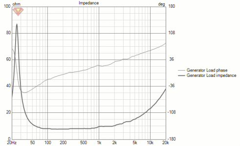
 
Yeah, but it's priorities. If we are talking about the same thing (breakup subharmonics), IMO one has to fight physical resonance with physical (discrete component) resonance if it is not possible to avoid the fight. See if this page makes more sense than I just did :) Best of course is to attempt to better sidestep with driver selection. Purifi certainly knows more about living with those cone materials than I do and I defer to them. This becomes personal preference/tradeoff. I will fight a 1.5kHz resonance harder than a 15.5kHz resonance down lower, but that's a personal position--and I will work hardest to minimize/avoid them with driver choice.

This is your process and you must follow your own thinking. My sense of you is that you must shine a flashlight in all the dark corners so it will not be fast :) All I will say is do everything--do it all and follow your head--but listen, too. A lot. For me, there are bigger fish to fry earlier--you may (will) differ. It is not hard to find people (including me) who will tell you exactly what they think you should do with your speakers, but this is your path :) Thank you for the links and for posting your updates.
 
Questions regarding notch filter (in series with the driver) design

I have been trying to design a notch filter for the Satori WO24P-8 driver to tame its breakup peak and also possibly reduce the rise in harmonic distortion associated with it. This may probably matter only if the Satori driver ends up in a application where it needs to be crossed higher than usual. Something like low pass filter applied around 1 kHz or so.
The ideas/guidelines for the notch filter design is taken (to the extent I understood it, for now) from a similar application for the purifi driver as described here:
https://purifi-audio.com/wp-content/uploads/2022/03/220211_R05-Notchfilter.pdf

The reason for trying to use this filter for the the Satori driver is due to the following reason:
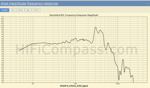
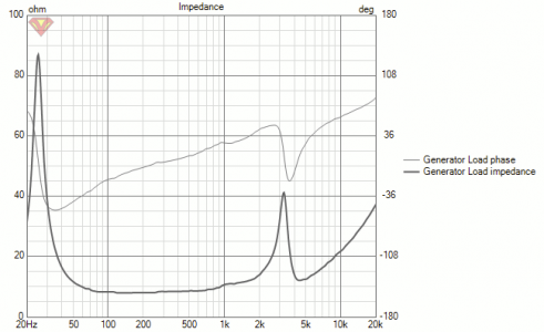
This driver has a big breakup peak around 3kHz as shown below:
1650805190754.png
If we take a look at the distortion plot of the driver as shown below, we can see a spike in 3rd order harmonic distortion (and second order harmonic distortion around 1kHz. This is a sub harmonic of the 3kHz frequency and I am assuming that the series notch filter reducing 3kHz breakup peaks will bring the distortion down).
1650805213079.png
I tried to compare between the following responses obtained by different notch configurations along with the lowpass filter for the driver and a little bit of passband linearization EQ.

Case-1)
No notch applied and corresponding filtered response and impedance plot (I have short circuited the filters and PEQ for the impedance plot)
1650805240392.png
1650805245993.png
1650805256472.png
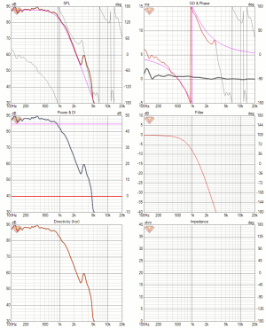
Case-2: A notch filter (notch-1) applied:
1650805279255.png
1650805284676.png
1650805295325.png
We have about 10dB more attenuation of the breakup peak and a rise in impedance magnitude (40ohm vs 12ohm without notch) around the breakup peak. The hope is that this impedance rise will also reduce the distortion.

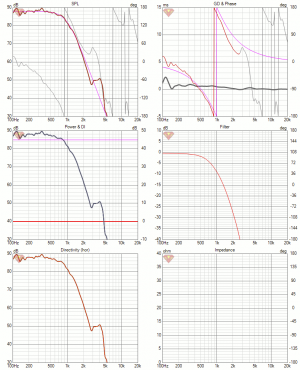
Case-3: Another notch filter (notch-2) and associated responses:
1650805319229.png
1650805325663.png
1650805333363.png
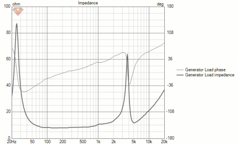
Please note the change in the frequency response around the 3kHz region and the 65ish ohm impedance magnitude around that frequency.

I understand that to see the effect of this whole thing properly, I should be taking/showing the distortion plots with application of each filter, but can we make useful conclusions/guidelines/observations without that for now?

Other questions regarding which implementation is better:
1) Should I aim for a plateau like suppression of the break up peak (notch-1) or the more rolling off type suppression with smaller peaks given by notch-2?
2) Also how do these impedances and their rise affect the amplifier's ability to drive the speaker, if at all there is any effect.?
3) Is there a guideline or some rule which says impedance variations we cause due to introduction of external elements as part of crossover/notch/frequency response shaping circuit shouldn't be higher (or should be lesser by some amount) compared to the the drivers impedance at its resonant frequency of around 25Hz?

Please let me know your suggestions/comments.

Thanks
Vineeth
 
I have been fortunate enough to get the answers to above questions from Lars Risbo himself.. :D
Here are his replies to above 3 questions (quoting his reply as such from my diyaudio thread hoping that it becomes useful to someone in future):

" 1) the speaker shows more of a shelving up response at 3k so this is not possible to kill completely with the notch.

2) shouldn’t be a concern for a reasonable quality amp

3) no but adding series impedance changes the T/S parms of a driver. A resistor in series increases Qes. Interestingly, an inductor is effectively reducing the Mms (fs and Qes up). I plan to write another app not about this fairly overlooked effect. A series inductor simply has a side effect and this may lead to a wrong response if the designer is not very careful. Typical acoustic measurements are gated and hence has poor bass resolution so this effect is only visible in real anechoic measurements "
 
Having extensively dabbed with active crossovers for some years, I have observed that correecting a speakers natural responce through filters (digital: active or analogue: passive) produces undesirable effects.
It is better to cross a driver within its passband with minimal crossover intervension and accurately work on the crossover region with the drivers it is aligned with.

However I applaud you for your extensive work.
But be careful and limit exposure to all the white noise and sine waves that we have to run for measurung. They have had a telling effect on my listening over the years. Ofcourse I was in a more risky environment like a car where the impact is the worst.
 
Having extensively dabbed with active crossovers for some years, I have observed that correecting a speakers natural responce through filters (digital: active or analogue: passive) produces undesirable effects.

Thank you @Kannan. It has been looking at yours, tcpip's, and some other FMs posts over past years that got me interested in designing a speaker for myself in the first place. :)
Can you tell more about what are some undesirable effects brought about by filtering?

In fact, I have the exact opposite experience regarding using filters for correction. Some drivers are unlistenable without filtering. One of them being the driver under discussion here: Satori WO24P.
I feel that this is a gem of a driver once it is handled and filtered properly :) This is after extensive hearing tests with this driver with all kinds of music I listen to and all kinds of rational EQ applied on it. Speakers natural responses may be corrected if the drivers can take it. A good majority of our typical home audio "hifi" drivers can't take it because of the limitations in various aspects in their design.
I agree that with filtering, we are often trying to correct a 3-dimensionsal anomaly (related to acoustics part of the speaker) using corrections in the 1-dimensional electrical signal domain. But some part of that is inevitable, I think at least for now.

It is better to cross a driver within its passband with minimal crossover intervension and accurately work on the crossover region with the drivers it is aligned with.
If there had been a single driver capable of delivering all that we wanted there would have been no need for multiway speakers. But as you said, if there are drivers which are made keeping in mind their intended use cases with other partnering drivers overall acoustic concept and construct, and equipment, choosing them would be the best. Less crossover, less correction, less "stress" on the driver etc. But there is always a tradeoff with drivers and preferences also come into play. An example being that if all we wanted were drivers with smooth frequency responses and requiring less filtering, we could have gone for well made polycone drivers. But most of them sacrifice on certain aspects. Be it higher cost, lesser detail retrieval from music, others, etc.

Also, in this study, I am trying to learn more about all these aspects. Hence it needs to be challenging. Otherwise it is boring. :D
I have had my easy speaker design and learning part with a pair of DIY Jeff Bagby designed tributes speakers and few others.
Now I want to push boundaries, whether it is in the learning part or design part.
I need to learn to squeeze out every possible bit of performance from designs and understand limitations :)

However I applaud you for your extensive work.
Thank you so much.
Your words/comments are amongst the very little encouragement I get on this forum. So I value it a lot :)
(on diyaudio forum it is a completely different story. So far I've got immense amount help from very very knowledgeable people like Kimmosto, Lars Risbo, fluid, augerpro, Juhazi, krivium, and so many other people in understanding several aspects in design of speakers)

But be careful and limit exposure to all the white noise and sine waves that we have to run for measurung. They have had a telling effect on my listening over the years. Ofcourse I was in a more risky environment like a car where the impact is the worst.
Sure. I have already taken note of this. In fact I have been contemplating on which hearing protection device I need to order over the past week. Just to be careful while doing the sweeps. I don't listen to very loud music in general anyway. Also I do sweeps at lower SPL levels mostly. But as you pointed out preserving hearing is the most important thing.
In fact I feel that the kind of building construction related noise near to places where I live/work is far more dangerous to my ears than the few sweeps I do. Wrong place/time to live in, I guess.. :D
 
Can you tell more about what are some undesirable effects brought about by filtering?
Sorry for this long post.

What I meant by using filters of various types before a driver essentially meant we are playing with the music signal to correct the driver, not physically correcting its fallacies.
I have never delved as extensively with raw drivers as you have done except for building my 4-way active setup in car.
Otherwise I was limited to the standard car audio drives which were provided as either 2-way or 3-way components sets.
The passive xo supplied (with details of the xo points and slope) with them usually gave us a good starting point while putting them into active configuration. Of course we used to measure the individual drivers for ratification.

My experience has been restricted to multi-way (2-way or more) setups and not full range drivers.
I prefer to pass a driver only within the frequencies where the impedance vagaries are minimal, irrespective of the amplifier being able to handle it. Even within that frequency bandwidth, I never boost a frequency if there is a dip, and never cut anything more than 2db.
I have noticed that cutting anymore than 2db creates a type of smearing effect or phase shift making the sound artificial or tonally incorrect.
Similarly while boosting a frequency we are actually forcing the driver play what it is not capable of. So I avoid that.

However to be truthful, I have technically never delved as deep as you have taken to tuning drivers.
In effect I prefer a set of drivers which I can blend within their natural pass band keeping any filtering to the minimal.

Before deciding on my 4-way, I did extensive reading and study of the parameters of various drivers offered by different companies, and most importantly, decided to stay within an intended budget.
I hit upon the Dayton Reference Series. The advantageous were price, local availability, availability of full technical details to first work on simulations and ofcourse hundreds of online reviews.
The RS100 wideband, RS180 midbass and the mini-AMT tweeters snugly fit for me in the 80hz to 20khz region in a 3-way active design. The fact that the driver material were ditto for RS100 and RS180 helped immensely.

Full range drivers are truly superior in this regard as best crossover is no crossover if you can find one that can do the full bandwidth without much of intermittent peaks.
 
Questions regarding notch filter (in series with the driver) design

I have been trying to design a notch filter for the Satori WO24P-8 driver to tame its breakup peak and also possibly reduce the rise in harmonic distortion associated with it. This may probably matter only if the Satori driver ends up in a application where it needs to be crossed higher than usual. Something like low pass filter applied around 1 kHz or so.
The ideas/guidelines for the notch filter design is taken (to the extent I understood it, for now) from a similar application for the purifi driver as described here:
https://purifi-audio.com/wp-content/uploads/2022/03/220211_R05-Notchfilter.pdf

The reason for trying to use this filter for the the Satori driver is due to the following reason:
This driver has a big breakup peak around 3kHz as shown below:
View attachment 68968
If we take a look at the distortion plot of the driver as shown below, we can see a spike in 3rd order harmonic distortion (and second order harmonic distortion around 1kHz. This is a sub harmonic of the 3kHz frequency and I am assuming that the series notch filter reducing 3kHz breakup peaks will bring the distortion down).
View attachment 68969
I tried to compare between the following responses obtained by different notch configurations along with the lowpass filter for the driver and a little bit of passband linearization EQ.

Case-1)
No notch applied and corresponding filtered response and impedance plot (I have short circuited the filters and PEQ for the impedance plot)
View attachment 68970
View attachment 68971
View attachment 68972
Case-2: A notch filter (notch-1) applied:
View attachment 68973
View attachment 68974
View attachment 68975
We have about 10dB more attenuation of the breakup peak and a rise in impedance magnitude (40ohm vs 12ohm without notch) around the breakup peak. The hope is that this impedance rise will also reduce the distortion.

Case-3: Another notch filter (notch-2) and associated responses:
View attachment 68976
View attachment 68977
View attachment 68978
Please note the change in the frequency response around the 3kHz region and the 65ish ohm impedance magnitude around that frequency.

I understand that to see the effect of this whole thing properly, I should be taking/showing the distortion plots with application of each filter, but can we make useful conclusions/guidelines/observations without that for now?

Other questions regarding which implementation is better:
1) Should I aim for a plateau like suppression of the break up peak (notch-1) or the more rolling off type suppression with smaller peaks given by notch-2?
2) Also how do these impedances and their rise affect the amplifier's ability to drive the speaker, if at all there is any effect.?
3) Is there a guideline or some rule which says impedance variations we cause due to introduction of external elements as part of crossover/notch/frequency response shaping circuit shouldn't be higher (or should be lesser by some amount) compared to the the drivers impedance at its resonant frequency of around 25Hz?

Please let me know your suggestions/comments.

Thanks
Vineeth
I am not sure if you have measured the Satori driver or simulating from the published specs. If its published specs, its mostly free-air without any box. Because of this, the driver suspension becomes very loose as the satori is a high compliance driver and the cone break-up is non-predictable in free-air. Once you mount this driver in a sealed box with the necessary stuffing, the suspension gets support from the box and the stiffness of the cone is well controlled and the peak response will not be present as displayed. It will be interesting for FMs to see whether the mounting of the satori on the box reduced the peaky response and report. Also you will need to simulate for the crossover with the actual measured FR and measured Z as mounting the driver in the box will also alter the impedance of the speaker system.

My 2 paise.
All measurements (impedance and angular frequency responses) in previous posts are actual measured data with the driver in a sealed box of about 45+ litres volume (made of 1inch thick xps foam, braced internally, and filled using dacron polyfill). All impedances have been measured using a Dayton DATS v3 and frequency responses using Dayton EMM-6 mic for semi dual channel and MiniDSP UMIK-1 mic for single channel measurements. Angular measurement is taken using box with driver/horn with driver on a rotating turntable as seen in posts on previous page. I use published specs only for guidance and not in the actual design process.
Of course, I will re do the measurements with the drivers in their actual cabinets once I get them.
The peak around 3kHz in the response of the Satori's is its break up peak, which will need to be controlled through the crossover.
 
So the greater plan of this design study is to use the twin Satori bass modules as the foundation for 2 way and 3 way speaker systems. This base/mid module will serve as the base with crossover ranging from 300Hz to max 1kHz in various configurations.. :)
In the works/plans are the following top modules (which handle higher frequencies)
1) A regular two way top module with SB15CAC30-8 mid + SB26CDC004 tweeter in a (hopefully) reduced diffraction cabinet
2) An ATH horn top module with a 1inch/1.4inch compression driver on a 3D printed ATH horn
3) A cardioid mid/waveguided tweeter 2 way like directiva R2 on ASR forum
4) A coaxial two way top module
5) An MEH (multiple entry horn) top module. This may even not need this Satori bass module at all.
6) Even though not yet finalized, I may also experiment with an open baffle mid if I get an opportunity.. :D

Objective is to study, explore and get a taste of different types of presentation and directivity control and how it interacts with the kind of listening spaces I have. :)
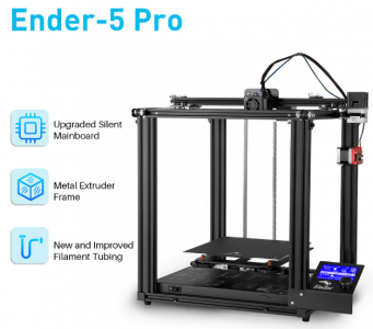
To help me with all this topmodule making business is the following 3D printer, which has already reached home.. ;) :D
1653048051953.png
 
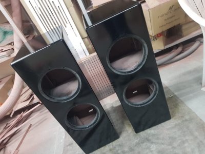
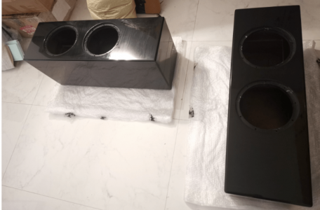
So they are home.. :D :D
They look very nice. But it seems like still there is looong way to go before they start playing some music.
I am tired moving these around.. :D
Will have to apply basic damping next. Maybe tomorrow.. :)

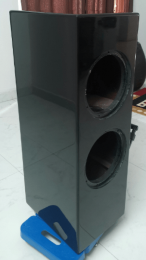
More pics:
1654338719322.png
1654338734880.png

1654338748800.png
1654338759549.png

Thanks
Vineeth
 
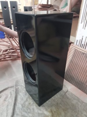
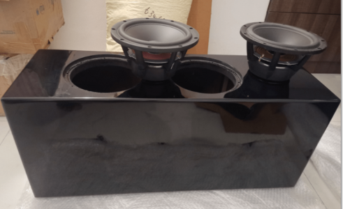
So I applied some damping material in the boxes and tried to get some nearfield frequency response and impedance measurements of a Satori WO24P-8 woofer fixed in the upper box of the cabinet as shown below.
1655466262125.png


Here is what the inside of the box looks like now with the driver removed:
1655466336411.png

Each driver has a 35ish litre sealed box of its own in the big enclosure. so even without the second driver, the current driver is supposed to have a sealed box of its own.
There is also a very small hole in the piece that separates the two driver boxes through which the wire comes out. I will close it fully, then attach the 2nd driver also and take measurements again. Probably that double hump impedance seen below is caused by this leak or some other. Need to find out.

Regarding damping I glued some Alubutyl damping sheets that I had on the side and back walls. Then covered it with 10mm thick acoustic felt material.
Then I noticed two impedance bumps one around 230Hz and around 460Hz. In order to try to get rid of them, I put 25mm thick Basotect G+ type melamine foam pad that I had on the top of the cabinet as seen in above pic, one at the bottom of the cavity and one piece somewhere around 1/3rd of the height. I also put a loose roll of polyfill in a cylinder form on top of that as seen in above pic.

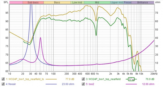
Here are the impedance measurements of the driver in free air and and box as treated above.
Also shown below is the nearfield frequency responses of the driver. Yellow plot below is my baffle step adjusted response and green, the not adjusted one .

1655473163327.png

Now the impedance blips around 230Hz and 460 Hz seems to be gone.
The impedance bump around 950Hz is there in both the free air plot and the driver in box plot.
Both curves are overlapping there. So I think it is driver related. (driver surround related issues)
Also similar anomalies are seen in hificompass's measurements of this driver as shown below:
Below nearfield response from hificompass shows a deep notch around 1kHz similar to mine.
1655471441768.png


Below is Hificompass impedance measurement zoomed in (it shows that blip around 1kHz and sort of its integer multiples):
1655472393087.png


More testing and coming soon. :D
 
Round-2 box measurements

Now I put both the woofers in the box and took each woofer's impedance measurements. All holes in the box were sealed.
Here is the pic of the setup:
1655549259086.png


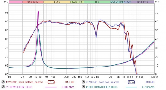
Here are the impedance plots and near field frequency responses for the top and bottom woofers in the box.
1655553040068.png


Looks like the impedance peak of the top woofer is higher but both woofers have the same width for impedance peak.
The top woofer box tuning frequency is about 45.6 Hz and the bottom woofers tuning is around 46.3 Hz.
Overall, the values look close. But is there something that needs to be done about the height of the impedance peaks, to bring them approximately to same level.
Does the 0.7Hz difference in tuning frequency matter?

Experts say the above minor differences are not worth loosing sleep over/digging deeper into :D

But i will play some low frequency tones through these drivers to loosen up the complete system and take the measurements again to see if there are differences :)
 
Last edited:
Overall, the values look close. But is there something that needs to be done about the height of the impedance peaks, to bring them approximately to same level.
Adding stuffing will reduce the impedance peak and removing stuffing will increase impedance peak. You can try adjustment after break-in.
 
Round-3 assembling full system and making it play before taking polar measurements due to curiosity :D

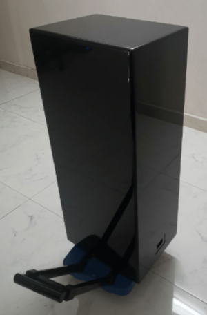
So i assembled the entire thing, paralled the woofers per cabinet, used the prototype crossovers i had developed for the foam box system and finally made it play as a 2 way system (SB audience Rosso 65CDN-T on Faitalpro LTH142 horn as the top module).

Here is me and my current system. The 6 channel amps are yet to arrive for 3/2.5 way crossover.
IMG-20220619-WA0002.jpg


I have no words.. It is so good :D Just happy even with the way it is playing even now.. :D
If the way it is currently playing is any indication of how much good it can be after proper measurements, and crossover based on it, I have succeeded in this personal pursuit to create a proper stereo system that suits my tastes.. (until the next better system comes along) :D

Ecstatic today. :D
I will try to take proper measurements in coming days and refine the entire system. Be it crossover-wise, placement of the speakers wise, and in as many aspects as i can to improve the overall system. :)
 
After a real lot of hard and boring work, this is the best i could do regarding taking measurements :)

Measurement session in progress
IMG_20220626_101042.jpg


Top woofer nearfield

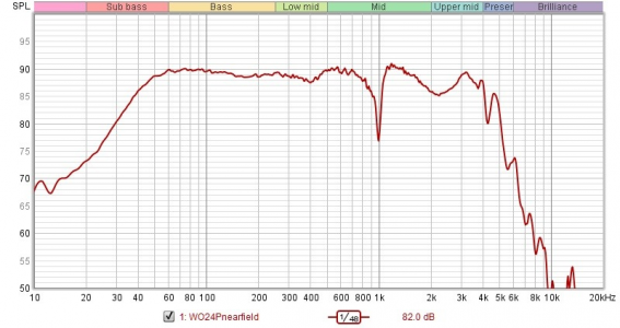
1656303621142.png


Top woofer farfield polar
wo24p_farfield_topwoofer.jpg


Rosso65CDNT on Faitalpro LTH142 horn polar

Rosso65CDNT_farfield.jpg


I can't take far field measurements of the bottom woofer. Tried a lot. But couldn't. Problem is I am unable to lift the cabinet high enough now to take measurements with center of the bottom woofer facing the mic at about 1m height. Anyway I am going to cross it over around 350Hz eventually. I may try to take a ground plane or nearfield measurement for it. And I will have to do some vituixcad adjustment for it.

First attempt at crossover
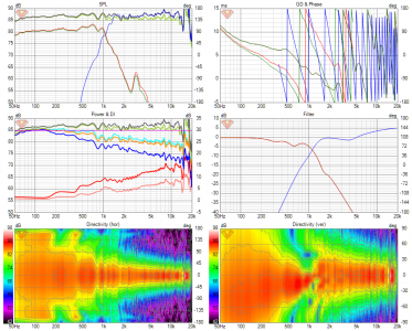
This is to get an idea about what can be done with these measurements.. :) The vertical polars maybe slightly wrong. I will try to study and use some document related to same that FM decibel had posted long back in VituixCAD thread and try to see what can be done. As next step i will try to simply the signal processing and the filter blocks involved. :)

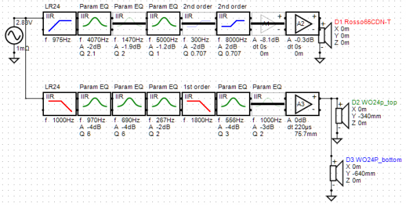
Crossover updated :D
1656265000075_2wayhorn_fullpolar3 XO-schema-1.png


1656303662147.png

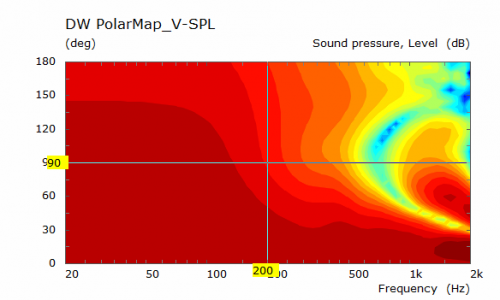
Probably, i think i will get a bit more energy and reduce cancellation and nulls around crossover in the vertical response, if i make this entire configuration 2.5 way and roll off one woofer earlier around 350Hz. The 2 woofer responses itself causes some lobing around crossover in vertical direction.

The two woofers themselves are causing some lobing around 1kHz
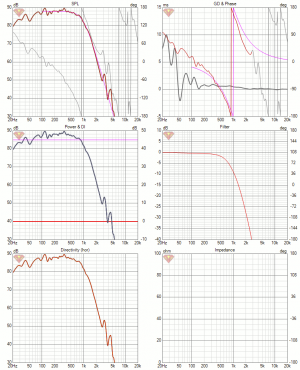
FM Fluid on diyaudio had shown something similar to this long back in his sims for twin woofer configuration as shown below if i understood it correctly
1656303675281.png

Thanks
Vineeth
 
FM fluid on diyaudio made me a crossover :)
It sounds amazing..... :D:D
So happy with the sound.. This is probably the crossover that is going to stay in this system configuration :)
Here is it:
2way_satori_rosso_CD_LR4 XO-schema-1.png
2way_satori_rosso_CD_LR4 Six-pack.png

Major difference I felt from previous crossover I had is some sort of energy/punch in male vocals. Sort of 3D soundstage and amazing ambient sounds which were not prominently heard earlier. All this at even low volumes. I don't listen at very high volumes, in general but at just enough to hear some bass come through.. :)
I tried to capture the sound via my mobile phone's camera. But it sounds terrible, echoey and nowhere close to the real thing.. :(
Anyway, this was the best I could do regarding capturing a video of the system playing:

I chose this piece of music because it has a lot of instruments, ambient sounds etc playing in the background of the vocals at different times. So all the train's ,vehicles, and rain sounds etc in the video is from the speakers :D

PS: The language used in the lyrics of the video (Malayalam) might seem like gibberish but it is my native language.. :D

Thanks
Vineeth
 
Experimental System - 2 in the works :)

With my current system singing amazingly well and given that I have a proper music system to listen to now, I am venturing into building some experimental system configurations all having in common the Satori WO24P-8 woofers based woofer box to take care of low end below 300Hz.

I had ordered a pair of Sica C 1.5CP 5.5 inch coaxial mid-tweeter drivers long back. I think I will be getting the drivers in a few weeks.. I plan to use them in a true 3 way configuration with my existing Satori WO24P-8 woofer box.
Now I am thinking about enclosures shapes for the coaxial driver.. :D

The first thoughts that i had was spherical enclosure which will be kept on top of the current woofer box and crossed over to the woofers somewhere above 300 Hz.. But seeing my 3D printer being able to print out good shapes I am thinking about 3D printing a teardrop-shaped enclosure for the driver. :D

To test my 3D printer's ability, I designed the enclosure I had in mind using fusion 360 and printed a prototype enclosure in PLA material with 20% gyroid infill (in 2 pieces which are threaded and can be joined). This is 30% scaled version of the actual enclosure size
Here is how it looks like at the moment:
IMG_20220708_154151.jpg


IMG_20220708_153045.jpg


IMG_20220708_153115.jpg


IMG_20220708_153017.jpg


The thought behind this enclosure shape was low diffraction and directivity control to the extent possible (though i don't know the exact amounts of it). I am hoping that having the coaxial driver with the mid acting as a waveguide for the tweeter may also help with some lessening of diffraction to some extent.
:)

Please let me know your thoughts about this.

Thanks
Vineeth
 
Wharfedale Linton Heritage Speakers in Red Mahogany finish at a Special Offer Price. BUY now before the price increase.
Back
Top