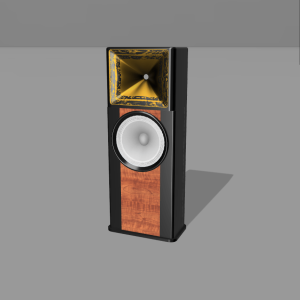
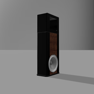
A multi-way speaker design around the EXAR 400 horn

Oh.. and that last video recording that I uploaded was a YouTube video of the song by Agam playing on my smartphone connected to the system via a DSP capable (for crossover and system-level EQ) Bluetooth amplifier board costing around 6-7k, which drives the whole speaker system :D
 
Thanks a ton for sharing the above :)

Now I fully understand where you are coming from, and why you are trying to control directivity. Even with the present Cardoid pattern, in your polar response plot, the reduction from 120 hz is very noticeable, from the otherwise wide directivity till almost 400 hz. And also your spectral decay, despite all the glass and bare walls is excellent. To be honest it is very close to my treated room :)

The horn is definitely doing its thing without having to treat reflection points which is the whole point of trying to control directivity.

I tried adding absorbers at first reflection points, and though it tamed early reflections to improve imaging, I felt it killed spatial cues that are the main tell tales of the recording environment. The reverbs and decays were gone. So the sound stage felt restricted, so eventually though everything sounded more detailed with better focus, I removed the absorbers. And have been thinking about " how to remove early reflections without effecting later reflections which contain reverb tails that need to linger on for some time". Your horn idea seems best. All the best for your endeavor and please keep updating as you make progress. Iam already invested in my next project, but will be following yours with a lot of interest :)
 
@Vineethkumar01 as an extension of my above thought process, Iam considering going OB next, as it is supposed to automatically have off axis cancellation, which iam expecting will reduce side wall early reflections without treatment. Do you think Iam on the right path :)

Already got all the drivers...so probably a little late to ask now 🤣
 
@Yelamanchili manohar : You are on the right path regarding sidewall interference reduction :)
If you can get a full-range dipole system, it has, by its nature, heavy attenuation to the sides.
You might want to be careful with the positioning of the system in the room.
Once you have the speakers, try pulling out the speakers into the room by different amounts.. Ideally we want the late reflections due to back waves to be late enough such that it contributes to the feeling of spaciousness
Excellent advise..thanks :)

That has been my main reason to go full range dipole. Will play around with speaker to front wall distance to get the right amount of late, front wall reflections as advised :)
 
Speaker response around MLP after a bit of room EQ.
1713708321460.png


I have not yet gone and done any all out room EQ through, keeping in mind that this is a temporary set up and due to lack of time.
But I have been listening to the system for short durations eatleast once in two days.
With this EQ, it sounds even better than before and my overall opinion about the sound haven't changed. It is awesome.. :D

This is mostly pointless but here is a sample recording just for fun :D

I recorded the same song just to do a side-by-side for fun so, sharing here too. I hope @Vineethkumar01, you did not mind.

 
Thanks Vineeth for answering my question.

I recorded the same song just to do a side-by-side for fun so, sharing here too. I hope @Vineethkumar01, you did not mind.


This is interesting. The difference in sound between this and what was posted before is large. Do you happen to have a response graph for your system, applicable when the recording was made?
 
Thanks Vineeth for answering my question.


This is interesting. The difference in sound between this and what was posted before is large. Do you happen to have a response graph for your system, applicable when the recording was made?
I do not know how to do it. Something that can be done with an app on phone? if yes, pls let me know and I will produce one.
 
I do not know how to do it. Something that can be done with an app on phone? if yes, pls let me know and I will produce one.

I am not familiar with phones regarding this. Normally people use a PC for this. It's all fine though, the important part is to enjoy the music. Have a good one and enjoy the music!
 
Back to the business of building boxes for the 2 15-inch drivers :)
All Thanks to @sadik for taking up this work and executing it in the best possible way.

Driver -1: Faital pro 15PR400 (upper bass to mids)
Box design: A traditional rectangular box with adequate bracing
Driver - 2: SB Audience NERO SW800 (lower bass region)
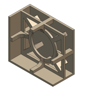
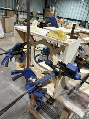
Box design: Specifically designed to hold the driver magnet and provide some amount of mechanical grounding for the big and heavy driver
1719402513366.png
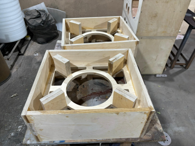
Work in progress

1719402851908.png
1719402924894.png

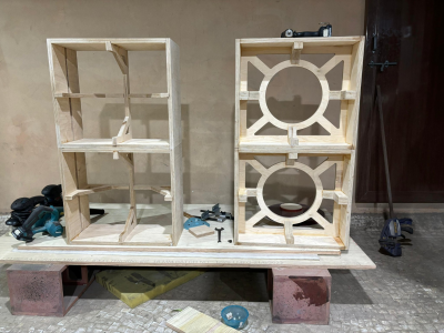
One set of boxes for the 15PR400s, on the left side of below pic (more bracing to go into that).
Another set for the NERO SW800s on the right side
1719402879154.png
 
I have planned for one more top module to test this dual woofer module. :D
It is a multiple-entry horn (MEH) with a 1.4/1 inch compression driver and closed back mids/cardioid radiating mids..
The entire multiple-entry horn module will then cross over to the dual woofer bottom module somewhere in the 200 to 400 Hz region.
Among the horns that fit the cabinets' dimensions involved in this project, I find the Tritonia waveguide (designed using ATH by Marcel Batik on Diyaudio) very suitable for this experiment.
The whole thing can potentially look something like this (the compression driver and associated mids, along with the midrange taps into the horn, are not shown) :D
1721320464431.png
1721320488698.png
 
A quick and very dirty Tritonia-based MEH prototype and preliminary measurements :D
This is not the actual Tritonia.
It is a scaled-down version with about 30ish cm width that Mabat had published on the ATH thread. The original one is about 43cm in width. Since this is a prototype, I decided to go with this smaller one as it was relatively easier to 3D print.


HF: SB audience Rosso 65 CDN-T
MF: 2 x Tymphany TC9FD8 in parallel (8x B&C 4NDF16 drivers already in hand.. ;) )

Mids radiate out through elliptical-shaped ports into the horn.

IMG20240722215253.jpg


IMG20240722215235.jpg


Right now the mids are open-back. Need to close it and test Next. But till then here are two sets of measurements of the Mids and CD taken separately from about 10cm from horn mouth and 1m away from horn mouth.

Measurements from 10cm away from horn mouth
1721669161581.png


Measurements from 1m away from horn mouth

1721669216226.png


The below distortion results are unreliable but still here it is..
Rosso CD distortion from 1m away
1721669436967.png


Same for 2xTC9FD in parallel on the horn
1721669453148.png


More measurements with closed back mids and polars will come when I get time.. :D

PS: Both drivers were measured with different input voltages as I accidentally turned the amp volume control after I took measurements of the CD on the horn

I wanted to fix the mids and the ports on the top and bottom of the horn instead of on the sides.. I mistakenly put them on sides while designing and saw the mistake only after 3D printing.. Also, seems like i was half asleep while doing the design since the driver cutout and screw holes for mids were missed and eventually I had to tape everything together for this experiment.. :D
 
For a first prototype based results, I am very encouraged by the results.. :)

But there are a few thoughts about how/where to going forward with this concept.
I am thinking if I can substitute the Rosso CD with a 1inch CD like the B&C DE 360 (need to buy) or the tymphany DFM 2535/2544 R (both of which I have in hand) to replace Rosso CD on this MEH experiment..

The mids seem to go as high as 1.5kHz or so.. Hence it looks like a waste of the Rosso CD.. Also, The B&C DE360 looks so clean (for a compression driver) upto 20kHz that I have not seen anything like it.. I also have 8 x 4NDF34 waiting to be used as a synergy mids instead of the TC9FD drivers..

With all the above potential driver changes, I want to keep the original size of the Tritonia Waveguide or slightly larger (430mm x 3xx mm) and use it with a 1inch driver so that once I put it in a baffle and add round overs around the edges, it will come to a total of about 520mm in width, which is exactly thr width of my 15inch driver cabinets.. It looks like I will have to custom-make a waveguide using ATH if I am going with these changes.
 
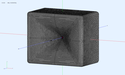
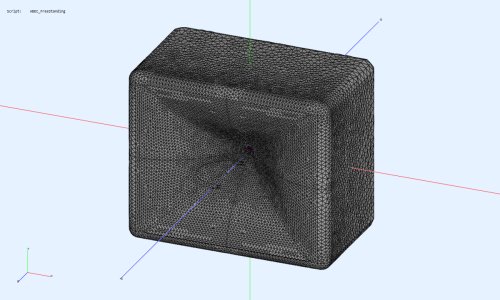
Based on above thoughts, I am trying out BEM simulations for a relatively bigger custom-designed waveguide in a box with rounded edges..
The waveguide dimensions are the following:

Width x height = 448.00 x 386.00 mm
Depth = 144.00 mm
Throat diameter = 25.4mm (1 inch)

This should give an idea about the frequency response polars.. :)
1721754899574.png

Fingers crossed.. Let's see how this turns out.. :D
 
Here is how things look like.. :D

I tried out a slightly larger waveguide derived from Tritonia but with a 1-inch throat using ATH and ABEC
Here is a comparison of infinite baffle vs waveguide in a box with 18mm rounding at the edges

Device width x height = 448.00 x 386.00 mm (17.638 x 15.197")
Device length = 144.00 mm (5.669")

Infinite baffle sims
1721809212501.png


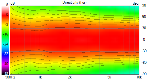
Normalized response curves from 0 to 90 degrees (Normalization using 10 degrees off-axis curve)
1721827802378.png


1721828056242.png


Waveguide in a box version
1721828264008.png


1721834484050.png


1721828320925.png


I am not sure about this.. It looks like the waveguide has a little too much directivity at 1kHz itself.
Even if I have cardioidish radiating mids crossing over around 1.5 kHz to the waveguide, its directivity of around 5-6dB might be less compared to that of the waveguide I think...
 
To give context, these are the directivities we are trying to match with crossover(s)

Dual 15inch woofer module (ideal) directivity
1721832416475.png


Above mentioned waveguide's directivity
1721833647074.png


These are good results I think.. But not the best possible.. :)
I am going to try out more experiments/sims to see how things can be changed and how it all affects the radiation
 
On with more sims/testing

1721997585429.png

I tried a smaller waveguide, less deep waveguide and 25mm rounding at edges. Here are simulation results for that..

Device width x height = 376.00 x 324.00 mm (14.803 x 12.756")
Device length = 120.00 mm (4.724")

1721896017767.png


1721896155518.png
 
Then I tried simulating a rounded cabinet of the same depth (310mm) as in the earlier case integrated with the waveguide..
Observing any differences between the results in the two cases is hard.
Here are the results..

In all below results, the flattening of axial response has been done w.r.t 20 degrees off axis..

Device width x height = 376.00 x 324.00 mm (14.803 x 12.756")
Device length = 120.00 mm (4.724")

Regular cabinet with 25mm rounding and 310mm depth
1721912114993.png


1721912289110.png


1721912317681.png


1721912344834.png


Curved cabinet with 25mm rounding and 310mm depth

1721912448630.png


1721912487232.png

1721912510169.png

1721912542194.png


Side-by-side comparison between regular cabinet and curved cabinet (if at all it appears side by side in the browsers others are using.. :D )

Regular cabinet (left) Curved cabinet (right)
1721912650330.png


1721912672320.png
 
I was curious about how it will all fit together to form a system, well at least in simulation land..:D
Here is a quick stitching of the MEH-waveguide described above without the curved cabinet and the dual 15inch woofer system with a sample crossover system implemented..
I have assumed that there will be one more cross between the mids on the MEH and the CD in it and it is not shown..
Another assumption is that the mids (closed back configuration) on the MEH waveguide will acquire whatever directivity the waveguide gives at lower frequencies

1721924214180.png


1721924232680.png


Directivity/horizontal polar pattern looks nice (I should say pretty awesome :D) on paper/screen I think... :P
 
Get the Award Winning Diamond 12.3 Floorstanding Speakers on Special Offer
Back
Top