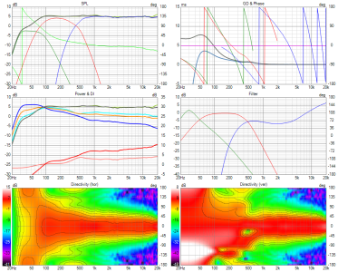
A multi-way speaker design around the EXAR 400 horn

On with more things done in the real world... :D

Prototype measurements

Here is the ugly cabinet made for the MEH using XPS foam and hot glue (I know that it will not win any prizes for looks or functionality.. That thing causes its own sweet resonances :p :D)
1721993042082.png


Measurements were made only out to 90 degrees. Measuremets were gated at 4ms..
Hence the masking of high Q resonances in the passband are also probably there..

Anyway, here is how the highs on Rosso 65CDN-T look like (Normalized 20 degrees off axis)

1721992906183.png


1721992964733.png


1721992975105.png


Now the mids (2xTC9FD in closed box of 10+ litres volume)
1721993343297.png


1721993353255.png


1721993363035.png


And here is a rough crossover that stitches together the two sets of drivers (Off course it can be done infinitely better :D )

1721994645744.png


1721994659284.png


With all the defects in construction, it looks surprisingly good I think.. :)
 
I am very encouraged by the results already.. :)
We have a point source (c-t-c spacing of drivers less than 1/4th wavelength at crossover) with very high dynamics capability and nice pattern control (with the MEH alone) down to 500ish Hz.. :)
Add the dual 15-inch woofer module, and we get directivity control down to less than 100 Hz and literally explosive dynamics in the full audio bandwidth from a point source.:)
Like this.. 😎
1721998386698.png
Time to get serious I think..

Here are the actual drivers I will be using per box on the final MEH
Shiny new things from TLHP are here.. :D

1721997404513.png


1721997423915.png
 
Last edited:
The edge termination business of the waveguide and connecting it to a rectangular box has been on my mind..
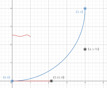
Till now, I have been using circular arcs to join the waveguide to the box that holds it. Inspired by comments from members over at diyaudio, I thought, why not use a super elliptic curve defined over one quadrant as the piece to connect the waveguide to the box instead of a circular arc.
So I took the parameters of the super ellipse (except parameter L) from the ATH profile definition (of this OSSE waveguide) and created a smaller super ellipse of L=44mm to serve as the edge termination.. This is how it looks :D
The waveguide alone is the yellow surface. The edge termination solid body has been extruded from the smaller (approximation using splines) super ellipse I created..
1722158565629.png


I haven't simulated the effect of this over the cirrcular arc in ABEC sims though.. I am feeling lazy to check that part.. :D

Here is the waveguide Joined to the box :D

1722159994791.png
 
Further studies and designs iterated overs hours and days..
My PC tirelessly did the number crunching over days and nights, and I finally found a good-looking waveguide with slightly smaller dimensions. :D

The main region why I liked this waveguide is because of the relative absence of wide-narrow-wide trends in the horizontal polar pattern and the gently sloping up sound power DI and ERDI.. :)
Vertical polars were clean anyway..

Here are the details of the waveguide.

Device width x height = 346.46 x 287.46 mm (13.640 x 11.317")
Device length = 115.00 mm (4.528")

40mm roundovers on all sides 25cm depth to the box..
1722756873984.png


1722756839072.png
 
Then I tried to make the waveguide slightly larger because we need a certain specific directivity pattern through the upper mids and treble region gently transitioning to meet a cardioidish radiating twin 15inch woofer system.

Here is the tiny bit larger and deeper waveguide

Device width x height = 357.62 x 296.53 mm (14.080 x 11.674")
Device length = 118.00 mm (4.646")

1722760575031.png


Predicted polars
1722760531857.png


1722760514803.png


Assuming the blips around 2.5 kHz are numerical issues... I really liked this waveguide.. :)
 
Now we try optimizing the entire structure further to try and get every last bit of performance available.. :)

As a first step, I tried the above waveguide in an elliptical enclosure with edge rounding formed using below shown cubic bezier curve.
Cubic bezier curves are super awesome in that they can literally form all kinds of usable curves with simple parameter adjustments. The curve formed below was trying to minimize the curvature of the transition from the waveguide edge to the back enclosure..

Here is the curve..
1723285819799.png


And the overall structure for simulation focussing on horizontal polars

1722768554847.png


Vertical polars are excluded from below directivity measurement due to lack of rounding on top and bottom edges in the sim
1722768605314.png


The dotted curves below are the DIs with the above enclosure with a cuboidal cabinet (shown in the above posts).
Solid curves overlayed on it are the ones from the elliptical back enclosure
1722768748500.png


I think I have come to the conclusion for this build. :D
I will make the MEH using the waveguide and cuboidal enclosure in the previous post.
I am not getting enough returns (in terms of simulation results) with complex enclosures and complex edge termination profiles with this particular waveguide..
Maybe it is time to build one and hear how it all comes together in terms of sound..
I will try to get the waveguide 3D printed first.. :)
 
And for that I did the cad design for this MEH waveguide..
Here is a view from the bottom
1723271549411.png


Here is one from the top
1723271587415.png


Looks like some alien space ship (or a kitchen sink :P) I think.. :D
Honestly speaking, all those "holes"/mid ports near the throat are not very confidence inspiring..
So I will print one more prototype and measure with the drivers I have before I move to final printing of a pair of these waveguides.. :)
 
I got the Bigger MEH waveguide printed, attached it to a cardboard box and took some quick and dirty measurements :)
1724299152087.png


Here is an on axis response plot of the DE 360 on the waveguide in 3 cases
1) All mid ports open (red, lot of wiggles)
2) Side mid ports closed (green, much less wiggles)
3) All mid ports closed (blue, slightly better than above but not by much)
1724299359680.png


I ended up using only the two drivers on top and bottom connected in parallel (and not the two on sides) because of response anomalies due to the holes in the sidewalls (mid ports) near the throat

Pic taken before closing side wall ports
1724299613975.png


1724299873372.png


DE 360 polars out to 90 degrees (normalization done 20 degrees off axis)
1724299481129.png


4NDF mid polars out to 90 degrees (normalization done 20 degrees off axis)
1724299585048.png


A first cut crossover
1724299687391.png


1724299703005.png


1724299711539.png


Impedance plots of the mids in parallel and DE 360, all drivers attached to the horn
1724299748582.png


Even with the issues due to resonances and other anomalies due to the flimsy cabinet construction, this look like good results I think
It feels like this MEH idea is worth pursuing.. :)
 
REW autoEQ'd response of the DE 360 CD on horn and the burst decay
1724310960344.png


1724310979744.png

Here is a comparison of the normalised sound power DI between the BEM sims I made and the measured results (only using 0 to 90 degree measurements).

Dotted line below is the SP DI from SIM
solid line is from actual measurements..
1724315983177.png


Looks really close I think.. 😎
 
With the above passive crossover, the crossover frequency is somewhere around 1150Hz
1724338389694.png


For such low crossover, maybe a more robust compression driver is needed I guess.
Below is the distortion profile of the DE 360 I measured on this horn (Probably not very accurate but shows the relative trends)
1724338502962.png


Anyway, I am happy with this active crossover, where the crossover frequency looks is 1350Hz
1724338993768.png


1724339003888.png


1724339026941.png


In that region the THD has climbed to only 0.2% and the driver is rolling off at 36dB per octave due to the effective high pass roll off
1724339334456.png


I think I probably need to look into phase related aspects also with the crossover, given that it is an MEH..
 
Just applying response inversion tricks for full range FIR filtering and 8th order Linkwitz-Riley filters at 1350Hz..
1724340984721.png


1724340995236.png


1724341171831.png


Now I am done.. :D
Based on the lessons learnt so far, I should probably plan to get the final printing of a pair of these waveguides with two drivers per waveguide done.. :)
a wave guide with two drivers on them: I think perlisten also reached to this conclusion the same way you experimented with;) anyway that’s helll lot of work from your side and to me, the best actual engineering effort anyone has ever put into designing in this forum :)
 
Hats off to your enduring spirit :)

Thats a lot of research and experimentation. And a lot of the stuff you mentioned went well over my head. But I can see where your goodselves are heading. Will fondly look forward to the completed build and listening impressions.
 
Thanks everyone for the encouragement..
This build has progressed further..
Here are some more details.. :)

Here was one last attempt to have the MEH waveguide accommodate all the 4 x 4NDF3416 drivers (in parallel)
1725466382791.png


1725466544524.png


1725466600155.png


This time, enhancements to the older design includes the following
1) All 4 mid ports (1 for each driver) are vertically oriented and close to the corners
2) Mid ports closer to throat than earlier
2) Mid port opening more upto into each mid driver's centre region
 
I have been trying to add a back cover to the MEH.. just some other shape other than a plain box...
This is based on the earlier observation that other than the overall depth of the backside, the low frequency directivity didn't care between plain old box and a more rounded elliptical backside.. Still I dont know how much impact this kind of shape will have..

Here are some pics of the MEH with and without the back cover
1726407902147.png


1726407928296.png


1726408005129.png

1726408043383.png


In other news.. @sadik did an awesome job on the cabinets.. I just can't thank him enough for all this hard work.. :)

Now here are the enclosures in need of some edge rounding (just for looks) and some painting and veneer finishing

Box for the 15PR400
1726408451031.png


Box for the SBaudience NERO SW800
1726408422858.png


Boxes stacked one on top of the other
1726408296516.png

1726408333913.png
 
Follow HiFiMART on Instagram for offers, deals and FREE giveaways!
Back
Top